Nissan Maxima Service and Repair Manual: ECM branch line circuit
Diagnosis Procedure
1.CHECK CONNECTOR
- Turn the ignition switch OFF.
- Disconnect the battery cable from the negative terminal.
- Check the following terminals and connectors for damage, bend and loose connection (unit side and connector side).
- Models without automatic drive positioner
- ECM
- Harness connector E30
- Harness connector M1
- Models with automatic drive positioner
- ECM
- Harness connector E29
- Harness connector B10
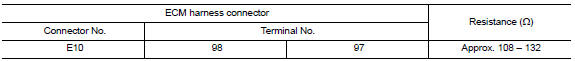
2.CHECK HARNESS FOR OPEN CIRCUIT
- Disconnect the connector of ECM.
- Check the resistance between the ECM harness connector terminals.
3.CHECK POWER SUPPLY AND GROUND CIRCUIT
Check the power supply and the ground circuit of the ECM. Refer to EC-157, "Diagnosis Procedure".
Is the inspection result normal?
 Main line between HVAC and ABS circuit
Diagnosis Procedure
1.CHECK CONNECTOR
Turn the ignition switch OFF.
Disconnect the battery cable from the negative terminal.
Check the following terminals and connectors for damage, bend and ...
 ADP branch line circuit
Diagnosis Procedure
1.CHECK CONNECTOR
Turn the ignition switch OFF.
Disconnect the battery cable from the negative terminal.
Check the following terminals and connectors for damage, bend and ...
Other materials:
U1000 CAN comm circuit
Description
DTC Logic
DTC DETECTION LOGIC
NOTE:
U1000 can be set if a module harness was disconnected and reconnected, perhaps
during a repair. Confirm
that there are actual CAN diagnostic symptoms and a present DTC by performing
the Self Diagnostic Result
procedure.
Diagnosis Proc ...
Exterior front
Engine hood
Wiper and washer switch
Windshield
Power windows
Door locks NISSAN Intelligent Key. Keys
Mirrors. Side view camera (if so equipped)
Tire pressure. Flat tire. Tire chains
Headlight and turn signal switch. Replacing bulbs
Fog light switch. Daytime running light syste ...
TCM branch line circuit
Diagnosis Procedure
1.CHECK CONNECTOR
Turn the ignition switch OFF.
Disconnect the battery cable from the negative terminal.
Check the following terminals and connectors for damage, bend and
loose connection (unit side and connector
side).
TCM
Harness connector F1
Harness con ...
Nissan Maxima Owners Manual
- Illustrated table of contents
- Safety-Seats, seat belts and supplemental restraint system
- Instruments and controls
- Pre-driving checks and adjustments
- Monitor, climate, audio, phone and voice recognition systems
- Starting and driving
- In case of emergency
- Appearance and care
- Do-it-yourself
- Maintenance and schedules
- Technical and consumer information
Nissan Maxima Service and Repair Manual

0.0055