
Nissan Maxima Service and Repair Manual: Brake tube and hose
Hydraulic Circuit
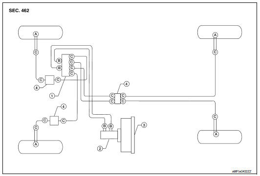
- Actuator
- Master cylinder
- Brake booster
- Connector
- Union bolt 18.2 N*m (1.9 kg-m, 13 ft-lb)
- Flare nut M12 22.1 N*m (2.3 kg-m, 16 ft-lb)
- Flare nut M10 16.2 N*m (1.7 kg-m, 12 ft-lb)
CAUTION:
- All hoses and piping (tubes) must be free from excessive bending, twisting and pulling.
- Make sure there is no interference with other parts when turning the steering wheel both clockwise and counterclockwise.
- The brake piping is an important safety part. If a brake fluid leak is detected, always disassemble the parts. Replace applicable part with a new one, if necessary.
- Be careful not to splash brake fluid on painted areas; it may cause paint damage. If brake fluid is splashed on painted areas, wash it away with water immediately.
- Do not bend or twist brake hose sharply, or strongly pull it.
- When removing components, cover connections so that no dirt, dust, or other foreign matter gets in.
- Refill with new specified brake fluid. Refer to MA-15, "FOR USA
AND CANADA : Fluids and Lubricants"
(for United States and Canada) or MA-16, "FOR MEXICO : Fluids and
Lubricants" (for Mexico).
- Do not reuse drained brake fluid.
FRONT BRAKE
FRONT BRAKE : Inspection
INSPECTION AFTER REMOVAL
CAUTION: Brake tubes and hoses are important safety parts. Always disassemble the parts and retighten their fittings, if a brake fluid leak is detected. Replace applicable part with a new one, if damaged part is detected.
- Check brake lines (tubes and hoses) and connections for fluid leaks, damage, twists, deformation, contacts with other parts, and loose connections. Replace any parts as necessary. Refer to BR-20, "Removal and Installation of Front Brake Piping and Brake Hose".
- While depressing brake pedal under a force of 785 N (80 kg, 177 lb) with engine running for approximately 5 seconds, check each part for fluid leaks.
REAR BRAKE
REAR BRAKE : Inspection
INSPECTION AFTER REMOVAL
CAUTION: Brake tubes and hoses are important safety parts. Always disassemble the parts and retighten their fittings, if a brake fluid leak is detected. Replace applicable part with a new one, if damaged part is detected.
- Check brake lines (tubes and hoses) and connections for fluid leaks, damage, twists, deformation, contacts with other parts, and loose connections. Replace any parts as necessary. Refer to BR-21, "Removal and Installation of Rear Brake Piping and Brake Hose".
- While depressing brake pedal under a force of 785 N (80 kg, 177 lb) with engine running for approximately 5 seconds, check each part for fluid leaks.
 Vacuum lines
Inspection
VISUAL INSPECTION
Check for improper assembly, damage and deterioration. Replace as necessary.
CHECK VALVE INSPECTION
Airtightness Inspection
Use a suitable tool to check the built ...

Other materials:
Removal and installation
POWER SOCKET
Removal and Installation
POWER SOCKET
NOTE: If the tool does not fit because of
the location of the power socket, further disassembly may be required. Refer
to IP-14, "Removal and Installation".
Removal
Remove the fuse for the power socket.
Insert one end of the Tool (A) i ...
Optical sensor
Description
The optical sensor converts the outside brightness (lux) to voltage and
transmits the optical sensor signal to the BCM.
Component Function Check
1.CHECK OPTICAL SENSOR SIGNAL BY CONSULT
CONSULT
Turn the ignition switch ON.
Select "OPTICAL SENSOR" of BCM (HEAD LAMP ...
M&A branch line circuit
Diagnosis Procedure
1.CHECK CONNECTOR
Turn the ignition switch OFF.
Disconnect the battery cable from the negative terminal.
Check the terminals and connectors of the combination meter for
damage, bend and loose connection
(unit side and connector side).
2.CHECK HARNESS FOR OPEN CI ...
Nissan Maxima Owners Manual
- Illustrated table of contents
- Safety-Seats, seat belts and supplemental restraint system
- Instruments and controls
- Pre-driving checks and adjustments
- Monitor, climate, audio, phone and voice recognition systems
- Starting and driving
- In case of emergency
- Appearance and care
- Do-it-yourself
- Maintenance and schedules
- Technical and consumer information
Nissan Maxima Service and Repair Manual

0.0069