Nissan Maxima Service and Repair Manual: Instrument panel assembly
Exploded View
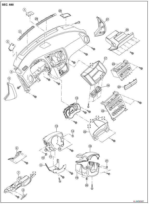
- Center speaker grille (if equipped)
- Tweeter speaker grille (LH)
- Front defroster grille (LH)
- Instrument panel
- Instrument side finisher (LH)
- Lower knee protector (LH)
- Instrument lower panel (LH)
- Fuse block cover
- Steering column lower cover (power tilt)
- Steering column screw finisher (LH) (power tilt)
- Steering column side cover (LH) (power tilt)
- Steering column side cover (RH) (power tilt)
- Steering column upper cover (power tilt)
- Steering column screw cover finisher (RH) (power tilt)
- Combination meter
- Multifunction switch (with color display) or A/C switch assembly (with monochrome display)
- Cluster lid D
- Steering column upper cover (manual tilt)
- Steering column lower cover (manual tilt)
- Steering column screw finisher (LH) (manual tilt)
- Steering column screw cover finisher (RH) (manual tilt)
- Cluster lid A
- Cluster lid C (with color display)
- Cluster lid C lower finisher (with monochrome display)
- Cluster lid C (with monochrome display)
- Glove box assembly
- Instrument side finisher (RH)
- Tweeter speaker grille (RH)
- Front defroster grille (RH)
 Clip
Clip
 Metal clip
Removal and Installation
CAUTION:
- Be careful not to scratch instrument panel pad and other parts.
- Before servicing, turn ignition switch OFF, disconnect both battery terminals and wait at least three minutes.
REMOVAL
- Disconnect the negative and positive battery terminals, then wait at least three minutes. Refer to PG-67, "Removal and Installation (Battery)".
- Remove the steering wheel. Refer to ST-17, "Removal and Installation".
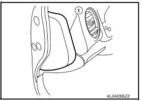
- Using a suitable tool, gently remove both instrument panel side finishers (1).
- Remove the instrument lower panel (LH) (1). Refer to IP-19, "Removal and Installation".
- Remove the steering column covers. Refer to IP-13, "Removal and Installation".
- Remove cluster lid A. Refer to IP-16, "Removal and Installation".
- Remove the combination meter. Refer to MWI-122, "Removal and Installation".
- Remove the glove box assembly. Refer to IP-20, "Removal and Installation".
- Remove the front passenger air bag module. Refer to SR-17, "Removal and Installation".
- Remove cluster lid D. Refer to IP-18, "Removal and Installation".
- Remove cluster lid C. Refer to IP-17, "Removal and Installation".
- Remove the display screen. Refer to AV-75, "Removal and Installation" (BASE AUDIO), AV-163, "Removal and Installation" (BOSE W/MONOCHROME DISPLAY), AV-484, "Removal and Installation" (BOSE W/COLOR DISPLAY) or AV-655, "Removal and Installation" (BOSE W/COLOR DISPLAY W/ NAVI).
- Remove the front pillar finishers (LH/RH). Refer to INT-24, "Removal and Installation".
- Remove the center console side finishers (LH/RH). Refer to IP-21, "Exploded View".
- Remove both tweeter speaker grilles and disconnect the harness connectors.
- Remove the tweeter speakers (LH/RH). Refer to AV-76, "Removal and Installation" (BASE AUDIO), AV- 166, "Removal and Installation" (BOSE W/MONOCHROME DISPLAY), AV-490, "Removal and Installation" (BOSE W/COLOR DISPLAY) or AV-661, "Removal and Installation" (BOSE W/COLOR DISPLAY W/ NAVI).
- Remove the center speaker (if equipped). Refer to AV-165, "Removal and Installation" BOSE W/MONOCHROME DISPLAY), AV-489, "Removal and Installation" (BOSE W/COLOR DISPLAY) or AV-660, "Removal and Installation" (BOSE W/COLOR DISPLAY W/NAVI).
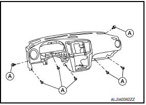
- Remove the remaining instrument panel screws (A).
- Disconnect the audio harness connectors located near the RH A-pillar.
- Lift the instrument panel high enough in order to disconnect the harness clip attached to the air duct, and all the necessary harness connectors, then remove the instrument panel.
INSTALLATION
Installation is in the reverse order of removal.
- If replacing the instrument panel, transfer all the necessary parts to the new instrument panel.

 Steering column covers
Removal and Installation
MANUAL TILT
Removal
Remove the steering column cover screw finishers (1) and then
remove the screws.
Remove the steering column upper cover (2).
Remove the stee ...
Other materials:
Precaution
PRECAUTIONSPrecaution for Supplemental
Restraint System (SRS) "AIR BAG" and "SEAT BELT
PRE-TENSIONER"
The Supplemental Restraint System such as "AIR BAG" and
"SEAT BELT PRE-TENSIONER", used along
with a front seat belt, helps to reduce the risk or severity of injury to the
driver and fron ...
P0122, P0123 TP sensor
Description
Electric throttle control actuator consists of throttle control motor,
throttle position sensor, etc. The throttle position sensor responds to
the throttle valve movement.
The throttle position sensor has two sensors. These sensors are a
kind of potentiometer which transfor ...
Trunk lid opener
Wiring Diagram
...
Nissan Maxima Owners Manual
- Illustrated table of contents
- Safety-Seats, seat belts and supplemental restraint system
- Instruments and controls
- Pre-driving checks and adjustments
- Monitor, climate, audio, phone and voice recognition systems
- Starting and driving
- In case of emergency
- Appearance and care
- Do-it-yourself
- Maintenance and schedules
- Technical and consumer information
Nissan Maxima Service and Repair Manual

0.0075