Nissan Maxima Service and Repair Manual: Body side trim
Exploded View
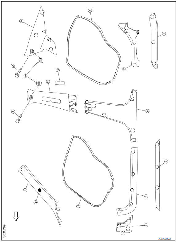
- Front pillar finisher
- Dash side lower finisher
- Front kicking plate
- Front sill cover
- Center pillar lower finisher
- Rear sill cover
- Rear kicking plate
- Rear body side welt
- Rear pillar finisher
- Screw cover
- Center pillar upper finisher
- Front seat belt adjuster cover
- Front body side welt
- Screw
- Tether clip
 Clip
Clip
 Pawl
Pawl
 Metal clip
 Front
Front
Removal and Installation
CAUTION:
- Wrap the tip of a suitable tool with a cloth when removing metal clips from finishers.
- When removing or installing body side welts, do not allow butyl seal to come in contact with pillar finishers.
FRONT PILLAR FINISHER
Removal
- Remove front body side welt partially.
- Disengage front pillar finisher (1) clip using a suitable tool (A).
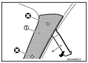
 : Clip
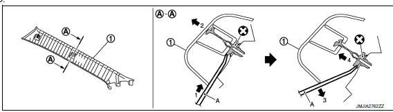
- Pull the front pillar finisher partially toward the vehicle.
- Insert the a suitable tool (A) between the front pillar finisher bottom side and body side to disengage the clip.
- Pull front pillar finisher upwards and use a suitable tool to cut both clips.
- Remove front pillar finisher (1).
Installation
Installation is in the reverse order of removal.
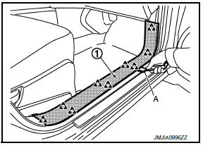
DASH SIDE LOWER FINISHER
Removal
- Release the clip and pawls using a suitable tool, then remove front kicking plate.
- Release the clips using a suitable tool, then remove dash side lower finisher.
Installation
Installation is in the reverse order of removal.
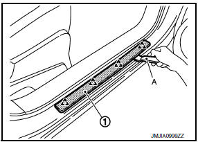
FRONT SILL PLATE COVER
Removal
Release the pawls using a suitable tool, then remove the front sill plate cover.
Installation
Installation is in the reverse order of removal.
FRONT BODY SIDE WELT
Removal
- Release the clip and pawls using a suitable tool, then remove front kicking plate.
- Release the clips and pawls using a suitable tool, then remove the center pillar lower finisher.
- Remove front body side welt from the body opening.
Installation
Installation is in the reverse order of removal.
FRONT KICKING PLATE INNER
Removal
- Disengage the pawls with a suitable tool (A) from the body.
- Remove front kicking plate inner (1).
 : Pawl
Installation
Installation is in the reverse order of removal.
FRONT KICKING PLATE OUTER
Removal
- Disengage the pawls from the body with a suitable tool (A).
- Remove front kicking plate outer (1)
 : Pawl
Installation
Installation is in the reverse order of removal.
REAR PILLAR FINISHER
Removal
- Partially remove rear body side welt.
- Remove screw cover, then remove the screw.
- Release the clips using a suitable tool, then remove rear pillar finisher.
Installation
Installation is in the reverse order of removal.
CENTER PILLAR UPPER FINISHER
Removal
- Release the clip and pawls using a suitable tool, then remove front kicking plate.
- Release the clip and pawl using a suitable tool, then remove rear kicking plate.
- Partially remove front and rear body side welts.
- Remove center pillar upper finisher cover and remove the screw.
- Remove front seat belt adjuster cover and shoulder anchor bolt. Refer to SB-6, "Exploded View".
- Release the clips and pawls using a suitable tool, then remove the center pillar lower finisher.
- Release the clips using a suitable tool, then remove center pillar upper finisher.
Installation
Installation is in the reverse order of removal.
REAR SILL PLATE COVER
Removal
Release the pawls using a suitable tool, then remove the rear sill plate cover.
Installation
Installation is in the reverse order of removal.
REAR KICKING PLATE
Removal
Release the clip and pawl using a suitable tool, then remove rear kicking plate.
Installation
Installation is in the reverse order of removal.
REAR BODY SIDE WELT
Removal
- Release the clip and pawl using a suitable tool, then remove rear kicking plate.
- Release the clips and pawls using a suitable tool, then remove the center pillar lower finisher.
- Remove rear body side welt from the body opening.
Installation
Installation is in the reverse order of removal.
 Rear door finisher
Exploded View
Rear door finisher
Step lamp
Armrest finisher
Rear power window switch finisher
Inside release handle escutcheon
Inside release handle
Flat head screws
&nb ...
 Rear parcel shelf finisher
Exploded View
With Sunshade
Rear parcel shelf finisher
Cover
Child anchor cover
Rear parcel shelf finisher (under side)
Dual lock fasteners
Clip
Front
Without ...
Other materials:
License plate lamp
Exploded View
License plate lamp
Removal and Installation
LICENSE PLATE LAMP
Removal
Remove the license lamp finisher. Refer to EXT-31, "Removal and
Installation".
Position trunk lid finisher aside. Refer to INT-36, "Exploded
View".
Remove the license plate lamp screw and ...
Chassis & body maintenance
Abbreviations: I = Inspect and correct or replace as necessary, R =
Replace,
NOTE:
Maintenance items with " " should be performed more frequently according
to "Maintenance under severe driving conditions".
(1) If towing a trailer, using a camper or a car-top carrier or driving on ro ...
Headlamp (LO) circuit
Description
The IPDM E/R (intelligent power distribution module engine room) controls the
headlamp low relay based on inputs from the BCM over the CAN communication
lines. When the headlamp low relay is energized, power flows through fuses 51
and 52, located in the IPDM E/R. Power then flows ...
Nissan Maxima Owners Manual
- Illustrated table of contents
- Safety-Seats, seat belts and supplemental restraint system
- Instruments and controls
- Pre-driving checks and adjustments
- Monitor, climate, audio, phone and voice recognition systems
- Starting and driving
- In case of emergency
- Appearance and care
- Do-it-yourself
- Maintenance and schedules
- Technical and consumer information
Nissan Maxima Service and Repair Manual

0.0059