Nissan Maxima Service and Repair Manual: Sound signal circuit
SATELLITE RADIO TUNER
SATELLITE RADIO TUNER : Description
Left and right channel audio signals are supplied from the satellite radio tuner to the AV control unit through the sound signal circuits.
SATELLITE RADIO TUNER : Diagnosis Procedure
LEFT CHANNEL
1.CHECK HARNESS
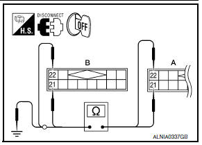
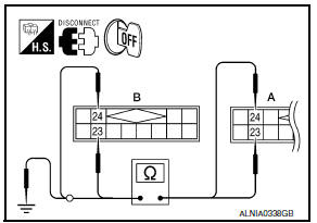
- Turn ignition switch OFF.
- Disconnect satellite radio tuner (factory installed) connector B111 and AV control unit connector M153.
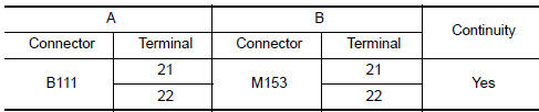
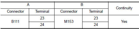
- Check continuity between satellite radio tuner (factory installed) connector B111 (A) and AV control unit connector M153 (B).
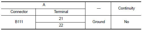
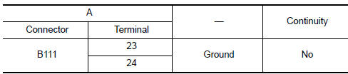
- Check continuity between satellite radio tuner (factory installed) connector B111 (A) and ground.
2.CHECK LEFT CHANNEL AUDIO SIGNAL
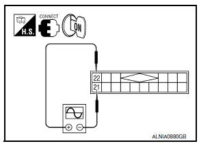
- Connect satellite radio tuner (factory installed) and AV control unit.
- Turn ignition switch ON.
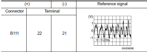
- Check signal between satellite radio tuner (factory installed) connector B111 terminals 21 and 22 with CONSULT or oscilloscope.
RIGHT CHANNEL
1.CHECK HARNESS
- Turn ignition switch OFF
- Disconnect satellite radio tuner (factory installed) connector B111 and AV control unit connector M153.
- Check continuity between satellite radio tuner (factory installed) B111 (A) and AV control unit M153 (B).
- Check continuity between satellite radio tuner (factory installed) connector B111 (A) and ground.
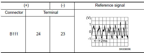
2.CHECK RIGHT CHANNEL AUDIO SIGNAL
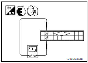
- Connect satellite radio tuner (factory installed) and AV control unit.
- Turn ignition switch ON.
- Check signal between satellite radio tuner (factory installed) connector B111 terminals 23 and 24 with CONSULT or oscilloscope.
 Communication signal circuit
SATELLITE RADIO TUNER
SATELLITE RADIO TUNER : Description
Communication signals are exchanged between the AV control unit and satellite
radio tuner using the communication
circuits.
SATELLITE R ...
 Microphone signal circuit
Description
Voice signals are transmitted from the microphone to the Bluetooth control
unit using the microphone signal
circuits.
Diagnosis Procedure
1.CHECK HARNESS BETWEEN BLUETOOTH CONTROL U ...
Other materials:
License plate lamp
Exploded View
License plate lamp
Removal and Installation
LICENSE PLATE LAMP
Removal
Remove the license lamp finisher. Refer to EXT-31, "Removal and
Installation".
Position trunk lid finisher aside. Refer to INT-36, "Exploded
View".
Remove the license plate lamp screw and ...
Vehicle security system
System Diagram
System Description
INPUT/OUTPUT SIGNAL CHART
OPERATION FLOW
SETTING THE VEHICLE SECURITY SYSTEM
Initial Condition
Ignition switch is in OFF position.
Disarmed Phase
When doors or trunk is open, the vehicle
security system is set in the dis ...
Conditions the remote start will not work
The remote start will not operate if any of the
following conditions are present:
"Remote Engine Start" is turned off in the
"Locking" section of the Vehicle Settings
menu.
The ignition switch is placed in the ON position.
The hood is not securely closed.
The hazard warning lights are ...
Nissan Maxima Owners Manual
- Illustrated table of contents
- Safety-Seats, seat belts and supplemental restraint system
- Instruments and controls
- Pre-driving checks and adjustments
- Monitor, climate, audio, phone and voice recognition systems
- Starting and driving
- In case of emergency
- Appearance and care
- Do-it-yourself
- Maintenance and schedules
- Technical and consumer information
Nissan Maxima Service and Repair Manual

0.0088