Nissan Maxima Service and Repair Manual: Microphone signal circuit
Description
Voice signals are transmitted from the microphone to the Bluetooth control unit using the microphone signal circuits.
Diagnosis Procedure
1.CHECK HARNESS BETWEEN BLUETOOTH CONTROL UNIT AND MICROPHONE
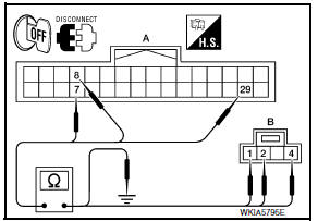
- Turn ignition switch OFF.
- Disconnect Bluetooth control unit connector and microphone connector.
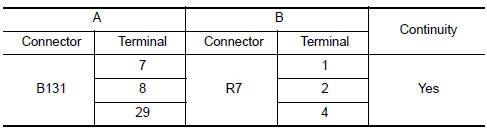
- Check continuity between Bluetooth control unit harness connector B131 (A) and microphone harness connector R7 (B).
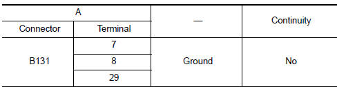
- Check continuity between Bluetooth control unit harness connector B131 (A) and ground.
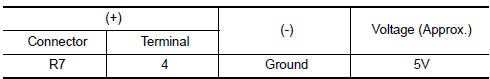
2.CHECK MICROPHONE POWER SUPPLY
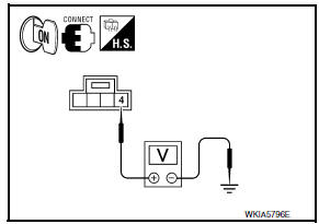
- Connect Bluetooth control unit connector and microphone connector.
- Turn ignition switch ON.
- Check voltage between microphone harness connector R7 terminal 4 and ground.
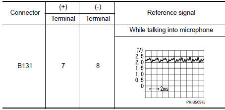
3.CHECK MICROPHONE SIGNAL
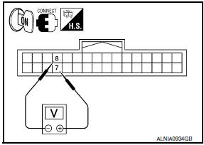
Check signal between Bluetooth control unit harness connector B131 terminals 7 and 8.
 Sound signal circuit
SATELLITE RADIO TUNER
SATELLITE RADIO TUNER : Description
Left and right channel audio signals are supplied from the satellite radio
tuner to the AV control unit through
the sound signal circuit ...

Other materials:
Meter control switch
Removal and Installation
REMOVAL
Disconnect the negative battery terminal. Refer
to PG-67, "Removal and Installation (Battery)".
Remove the cluster lid A. Refer to IP-16,
"Removal and Installation".
Detach the combination meter control switch
harnes ...
Rear door speaker
Removal and Installation
REMOVAL
Remove the rear door finisher. Refer to INT-21, "Removal and
Installation".
Remove the rear door speaker screws (A).
Disconnect the harness connector (B) from the rear door speaker
(1) and remove.
INSTALLATION
Installation is in the reverse orde ...
B257B, B257C ambient sensor
Description
COMPONENT DESCRIPTION
Ambient Sensor
The ambient sensor (1) is installed to the front bumper
reinforcement.
It detects ambient temperature and converts it into a resistance
value which is then input into the A/C auto amp.
Ambient Sensor Circuit
AMBIENT TEMPERATUR ...
Nissan Maxima Owners Manual
- Illustrated table of contents
- Safety-Seats, seat belts and supplemental restraint system
- Instruments and controls
- Pre-driving checks and adjustments
- Monitor, climate, audio, phone and voice recognition systems
- Starting and driving
- In case of emergency
- Appearance and care
- Do-it-yourself
- Maintenance and schedules
- Technical and consumer information
Nissan Maxima Service and Repair Manual

0.0065