Nissan Maxima Service and Repair Manual: Subwoofer
Description
The audio unit sends audio signals to the subwoofer amp. The subwoofer amp. amplifies the audio signals before sending them to the subwoofers using the audio signal circuits.
Diagnosis Procedure
1.CONNECTOR CHECK
Check the audio unit, subwoofer amp. and subwoofer connectors for the following:
- Proper connection
- Damage
- Disconnected or loose terminals
2.HARNESS CHECK
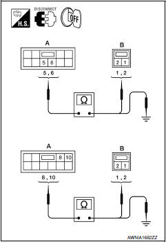
- Disconnect subwoofer amp. connector B21 and suspect subwoofer connector.
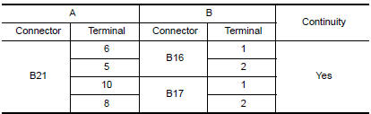
- Check continuity between subwoofer amp. harness connector B21 (A) and suspect subwoofer harness connector (B).
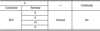
- Check continuity between subwoofer harness connector B21 (A) and ground.
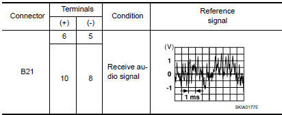
3.REAR SUBWOOFER SIGNAL CHECK
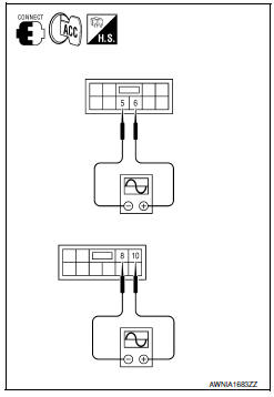
- Connect subwoofer amp. connector B21 and suspect subwoofer connector.
- Turn ignition switch to ACC.
- Push POWER switch.
- Check the signal between subwoofer amp. harness connector B21 terminals with CONSULT or oscilloscope.
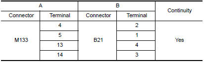
4.HARNESS CHECK
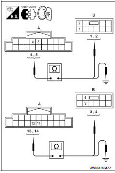
- Disconnect audio unit connector M133 and subwoofer speaker amp. connector B21.
- Check continuity between audio unit harness connector M133 (A) and subwoofer amp. harness connector B21 (B).
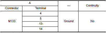
- Check continuity between audio unit harness connector M133 (A) terminal and ground.
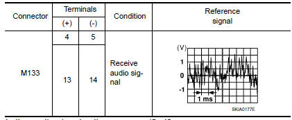
5.SUBWOOFER SIGNAL CHECK
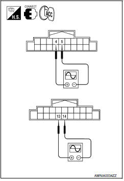
- Connect audio unit connector M133 and subwoofer amp. connector B21.
- Turn ignition switch to ACC.
- Push "POWER" switch.
- Check the signal between audio unit harness connector M133 terminals with CONSULT or oscilloscope.
 Rear door speaker
Description
The audio unit sends audio signals to the rear door speakers using the rear
door speaker circuits.
Diagnosis Procedure
1.CONNECTOR CHECK
Check the audio unit and speaker connectors f ...
 Steering switch
Description
When one of the steering wheel audio control switches is pushed, the
resistance in steering switch circuit changes depending on which button is
pushed.
Diagnosis Procedure
1.CHECK S ...
Other materials:
B2555 stop lamp
Description
BCM detects the stop lamp status and confirms the stop
lamp switch ON/OFF status. BCM confirms the
engine start condition according to the stop lamp switch ON/OFF status.
DTC Logic
DTC DETECTION LOGIC
DTC CONFIRMATION PROCEDURE
1.PERFORM DTC CONFIRMATION PROCEDURE
...
Power window serial link
POWER WINDOW MAIN SWITCH
POWER WINDOW MAIN SWITCH : Description
Main power window and door lock/unlock switch, power window and door
lock/unlock switch RH and BCM
communicate via the power window serial link.
The keyless power window down signal is transmitted from BCM to
main power ...
Insufficient cooling
Component Function Check
Symptom
Insufficient cooling
No cool air comes out. (Airflow volume is normal.)
INSPECTION FLOW
1. CONFIRM SYMPTOM BY PERFORMING OPERATION CHECK - TEMPERATURE DECREASE
Press the AUTO switch.
Turn temperature control switch (driver side) counterclockwise
u ...
Nissan Maxima Owners Manual
- Illustrated table of contents
- Safety-Seats, seat belts and supplemental restraint system
- Instruments and controls
- Pre-driving checks and adjustments
- Monitor, climate, audio, phone and voice recognition systems
- Starting and driving
- In case of emergency
- Appearance and care
- Do-it-yourself
- Maintenance and schedules
- Technical and consumer information
Nissan Maxima Service and Repair Manual

0.0076