Nissan Maxima Service and Repair Manual: Communication signal circuit
SATELLITE RADIO TUNER
SATELLITE RADIO TUNER : Description
Communication signals are exchanged between the AV control unit and satellite radio tuner using the communication circuits.
SATELLITE RADIO TUNER : Diagnosis Procedure
1.CHECK HARNESS - 1
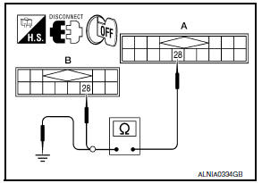
- Turn ignition switch OFF.
- Disconnect satellite radio tuner (factory installed) connector B111 and AV control unit connector M153.
- Check continuity between satellite radio tuner (factory installed) harness connector B111 (A) terminal 28 and AV control unit harness connector M153 (B) terminal 28.
- Check continuity between satellite radio tuner (factory installed) harness connector B111 (A) terminal 28 and ground.
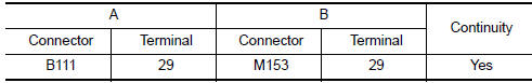
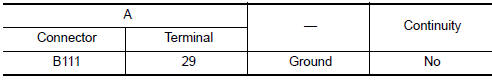
2.CHECK HARNESS - 2
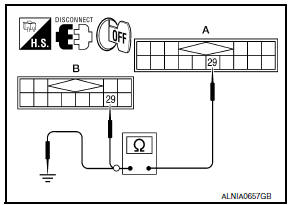
- Check continuity between satellite radio tuner (factory installed) harness connector B111 (A) terminal 29 and AV control unit harness connector M153 (B) terminal 29.
- Check continuity between satellite radio tuner (factory installed) harness connector B111 (A) terminal 29 and ground.
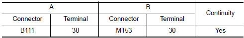
3.CHECK HARNESS - 3
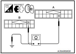
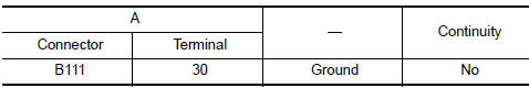
- Check continuity between satellite radio tuner (factory installed) harness connector B111 (A) terminal 30 and AV control unit harness connector M153 (B) terminal 30.
- Check continuity between satellite radio tuner (factory installed) harness connector B111 (A) terminal 30 and ground.
4.CHECK REQ1 SIGNAL
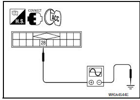
- Connect satellite radio tuner (factory installed) connector and AV control unit connector.
- Turn ignition switch to ACC.
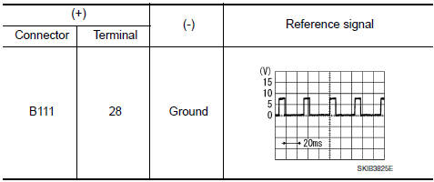
- Check signal between satellite radio tuner (factory installed) harness connector B111 terminal 28 and ground with CONSULT or oscilloscope
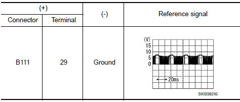
5.CHECK TXD SIGNAL
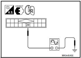
Check signal between satellite radio tuner (factory installed) harness connector B111 terminal 29 and ground with CONSULT or oscilloscope
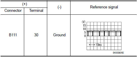
6.CHECK RXD SIGNAL
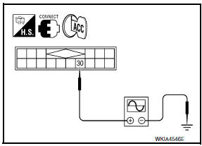
Check signal between satellite radio tuner (factory installed) harness connector B111 terminal 30 and ground with CONSULT or oscilloscope.
 Steering switch
Description
When one of the steering wheel audio control switches is pushed, the
resistance in the steering wheel audio
control switch circuit changes, depending on which button is pushed.
Diagn ...
 Sound signal circuit
SATELLITE RADIO TUNER
SATELLITE RADIO TUNER : Description
Left and right channel audio signals are supplied from the satellite radio
tuner to the AV control unit through
the sound signal circuit ...
Other materials:
Intelligent key warning buzzer
Description
Answers back and warns for an inappropriate operation.
Component Function Check
1. CHECK FUNCTION
With CONSULT
Check Intelligent Key warning buzzer OUTSIDE BUZZER in Active Test mode.
Diagnosis Procedure
1. CHECK INTELLIGENT KEY WARNING BUZZER
Check voltage between BCM connecto ...
Removal and installation
EXHAUST SYSTEM
Exploded View
Front exhaust tube
Ring gasket
Front exhaust tube stay
Front exhaust tube bracket
Gasket
Center exhaust tube rubber hanger
Center exhaust tube
Center exhaust tube hanger
Rear muffler bracket (RH)
Rear muffler (RH)
Rear muffler bracket (LH) ...
P1726 throttle control signal
Description
The electric throttle control actuator consists of
throttle control motor, accelerator pedal position sensor, throttle
position sensor, etc. The actuator sends a signal to the ECM, and ECM sends the
signal to TCM via CAN
communication.
DTC Logic
DTC DETECTION LOGIC
DTC CONF ...
Nissan Maxima Owners Manual
- Illustrated table of contents
- Safety-Seats, seat belts and supplemental restraint system
- Instruments and controls
- Pre-driving checks and adjustments
- Monitor, climate, audio, phone and voice recognition systems
- Starting and driving
- In case of emergency
- Appearance and care
- Do-it-yourself
- Maintenance and schedules
- Technical and consumer information
Nissan Maxima Service and Repair Manual

0.0056