Nissan Maxima Service and Repair Manual: Steering switch
Description
When one of the steering wheel audio control switches is pushed, the resistance in the steering wheel audio control switch circuit changes, depending on which button is pushed.
Diagnosis Procedure
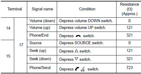
1.CHECK STEERING SWITCH RESISTANCE
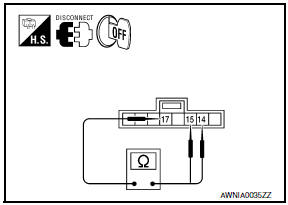
- Disconnect steering switch connector M88.
- Check resistance between steering switch connector terminals
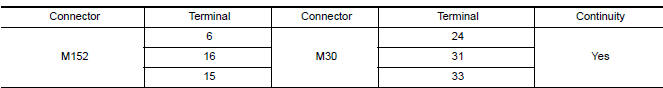
2.CHECK HARNESS BETWEEN COMBINATION SWITCH(SPIRAL CABLE) AND AV CONTROL UNIT
- Disconnect AV control unit connector M152.
- Check continuity between AV control unit harness connector M152 and combination switch(spiral cable) harness connector M30.
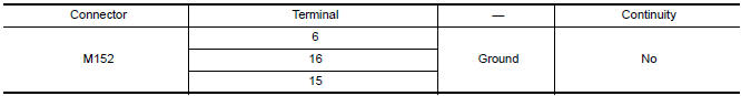
- Check continuity between AV control unit connector M152 and ground.
3.COMBINATION SWITCH(SPIRAL CABLE) CHECK
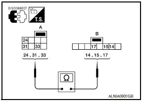
- Disconnect combination switch(spiral cable) connector M88.
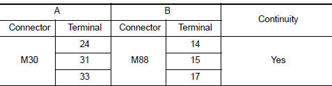
- Check continuity between combination switch(spiral cable) harness connector M30 (A) and M88 (B).
 AMP on signal circuit
Description
When the audio system is turned on, a voltage signal is supplied from the AV
control unit to the BOSE speaker
amp. When this signal is received, the BOSE speaker amp. will turn on.
D ...
 Communication signal circuit
SATELLITE RADIO TUNER
SATELLITE RADIO TUNER : Description
Communication signals are exchanged between the AV control unit and satellite
radio tuner using the communication
circuits.
SATELLITE R ...
Other materials:
Starting the engine
1. Apply the parking brake.
2. Move the shift lever to P (Park) or N (Neutral).
P (Park) is recommended.
The starter is designed not to operate if
the shift lever is in any of the driving
positions.
3. Push the ignition switch to the ON position.
Depress the brake pedal and push the ign ...
AV branch line circuit
Diagnosis Procedure
1.CHECK CONNECTOR
Turn the ignition switch OFF.
Disconnect the battery cable from the negative terminal.
Check the terminals and connectors of the AV control unit for
damage, bend and loose connection (unit
side and connector side).
2.CHECK HARNESS FOR OPEN CIRC ...
Unexpected pedal reaction
Diagnosis Procedure
1.CHECK BRAKE PEDAL STROKE
Check brake pedal stroke.
2.CHECK FUNCTION
Disconnect ABS actuator and electric unit (control unit) connector to
deactivate ABS. Check if braking force is
normal in this condition.Connect connector after inspection.
3.CHECK WHEEL SENSOR AND SEN ...
Nissan Maxima Owners Manual
- Illustrated table of contents
- Safety-Seats, seat belts and supplemental restraint system
- Instruments and controls
- Pre-driving checks and adjustments
- Monitor, climate, audio, phone and voice recognition systems
- Starting and driving
- In case of emergency
- Appearance and care
- Do-it-yourself
- Maintenance and schedules
- Technical and consumer information
Nissan Maxima Service and Repair Manual

0.0061