Nissan Maxima Service and Repair Manual: Door motor
Exploded View
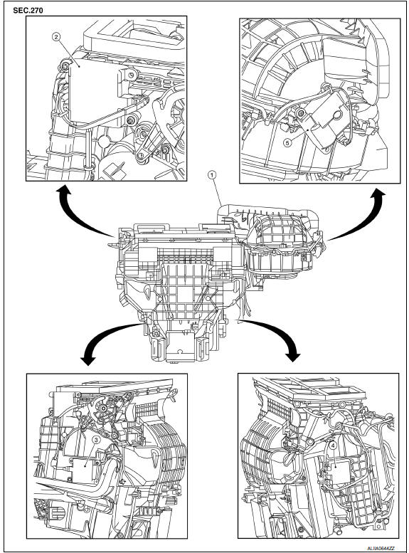
- Heating and cooling unit assembly
- Mode door motor
- Air mix door motor (driver side)
- Air mix door motor (passenger side)
- Intake door motor
INTAKE DOOR MOTOR
INTAKE DOOR MOTOR: Removal and Installation
REMOVAL
- Remove the glove box assembly. Refer to VTL-16, "BLOWER UNIT: Removal and Installation".
- Remove the remote keyless entry receiver and bracket to reposition out of the way.
- Disconnect the harness connector from the intake door motor.
- Remove the intake door motor screws and intake door motor from the blower unit.
INSTALLATION
Installation is in the reverse order of removal.
MODE DOOR MOTOR
MODE DOOR MOTOR: Removal and Installation
REMOVAL
- Remove the combination meter. Refer to MWI-122, "Removal and Installation".
- Remove the BCM. Refer to BCS-79, "Removal and Installation".
- Disconnect the harness connector from the mode door motor.
- Remove the mode door motor screws and the mode door motor.
INSTALLATION
Installation is in the reverse order of removal.
AIR MIX DOOR MOTOR
AIR MIX DOOR MOTOR: Removal and Installation - Air Mix Door Motor (Driver Side)
REMOVAL
- Remove the instrument lower panel LH. Refer to IP-19, "Removal and Installation".
- Remove the upper floor connecting duct (LH). Refer to HA-47, "Exploded View".
- Remove the tire pressure receiver.
- Disconnect the harness connector from the air mix door motor.
- Remove the air mix door motor screws and the air mix door motor (driver side).
INSTALLATION
Installation is in the reverse order of removal.
AIR MIX DOOR MOTOR: Removal and Installation - Air Mix Door Motor (Passenger Side)
REMOVAL
- Remove the glove box assembly. Refer to IP-19, "Removal and Installation".
- Remove the upper floor connecting duct (RH). Refer to HA-47, "Exploded View".
- Disconnect the harness connector from the air mix door motor.
- Remove the air mix door motor screws and the air mix door motor (passenger side).
INSTALLATION
Installation is in the reverse order of removal.
 Refrigerant pressure sensor
Removal and Installation
REMOVAL
Discharge the refrigerant. Refer to HA-28, "Recycle Refrigerant".
Remove the core support upper cover.
Disconnect the harness connector from the ref ...
 Basic inspection
INSPECTION AND ADJUSTMENT
Operational Check
DESCRIPTION
The purpose of the operational check is to check that the individual system
operates normally
Conditions: Engine running at normal operati ...
Other materials:
RGB AREA (YS) signal circuit
Description
Transmits the display area of RGB image displayed by AV control unit with RGB
area (YS) signal to display unit.
Diagnosis Procedure
1.CHECK CONTINUITY RGB AREA (YS) SIGNAL CIRCUIT
Turn ignition switch OFF.
Disconnect display unit connector M141 and AV control unit
conne ...
The ICC switch
The system is operated by the
CRUISE switch and four control
switches,
all mounted on the steering wheel.
1. DISTANCE switch:
Changes the vehicle's following distance:
Long
Middle
Short
2. RES+ switch:
Resumes set speed or increases speed incrementally.
3. CANCEL switch:
D ...
Basic inspection
DIAGNOSIS AND REPAIR WORK FLOW
Work Flow
OVERALL SEQUENCE
DETAILED FLOW
1.GET INFORMATION FOR SYMPTOM
Get detailed information from the customer about the symptom (the condition
and the environment when the
incident/malfunction occurred).
2.CONFIRM THE SYMPTOM
Try to confirm the sympt ...
Nissan Maxima Owners Manual
- Illustrated table of contents
- Safety-Seats, seat belts and supplemental restraint system
- Instruments and controls
- Pre-driving checks and adjustments
- Monitor, climate, audio, phone and voice recognition systems
- Starting and driving
- In case of emergency
- Appearance and care
- Do-it-yourself
- Maintenance and schedules
- Technical and consumer information
Nissan Maxima Service and Repair Manual

0.0088