Nissan Maxima Service and Repair Manual: Vehicle security system
System Diagram
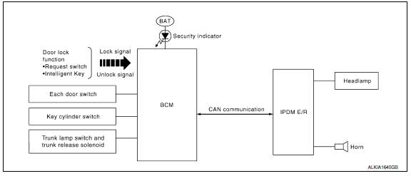
System Description
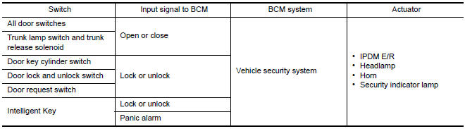
INPUT/OUTPUT SIGNAL CHART
OPERATION FLOW
SETTING THE VEHICLE SECURITY SYSTEM
Initial Condition
-
Ignition switch is in OFF position.
Disarmed Phase
-
When doors or trunk is open, the vehicle security system is set in the disarmed phase on the assumption that the owner is inside or near the vehicle.
-
When the vehicle security system is in the disarmed phase, the security indicator lamp blinks every 2.4 seconds.
Pre-armed Phase and Armed Phase
When the following operation 1 or 2 is performed, the vehicle security system turns into the "pre-armed" phase. (The security indicator lamp illuminates.)
-
BCM receives LOCK signal from front door key cylinder switch or Intelligent Key, after trunk and all doors are closed.
-
Trunk and all doors are closed after front doors are locked by key or door lock and unlock switch.
The security indicator lamp illuminates for 30 seconds. Then, the system automatically shifts into the "armed" phase.
CANCELING THE SET VEHICLE SECURITY SYSTEM
When one of the following operations is performed, the armed phase is canceled.
-
Unlock the doors with the key or Intelligent Key.
-
Turn ignition switch to "ON" or "ACC" position.
CANCELING THE ALARM OPERATION OF THE VEHICLE SECURITY SYSTEM
When unlocking the door with the key or Intelligent Key, the alarm operation is canceled.
ACTIVATING THE ALARM OPERATION OF THE VEHICLE SECURITY SYSTEM
Check that the system is in the armed phase. (The security indicator lamp blinks every 2.4 seconds.) When the following operation 1 or 2 is performed, the system sounds the horns and flashes the headlamps for about 50 seconds.
-
Trunk or any door is opened during armed phase.
-
Disconnecting and connecting the battery connector before canceling armed phase.
PANIC ALARM OPERATION
Intelligent Key system will not operate horn and headlamps if the ignition switch is in the ACC or ON position.
When the Intelligent Key system is triggered, ground is supplied intermittently to both headlamp relay and horn relay.
When headlamp relay and horn relay are energized, then power is supplied to headlamps (LH and RH) and horns (HIGH and LOW).
The headlamp flashes and the horn sounds intermittently.
The alarm automatically turns off after 50 seconds or when BCM receives any signal from Intelligent Key.
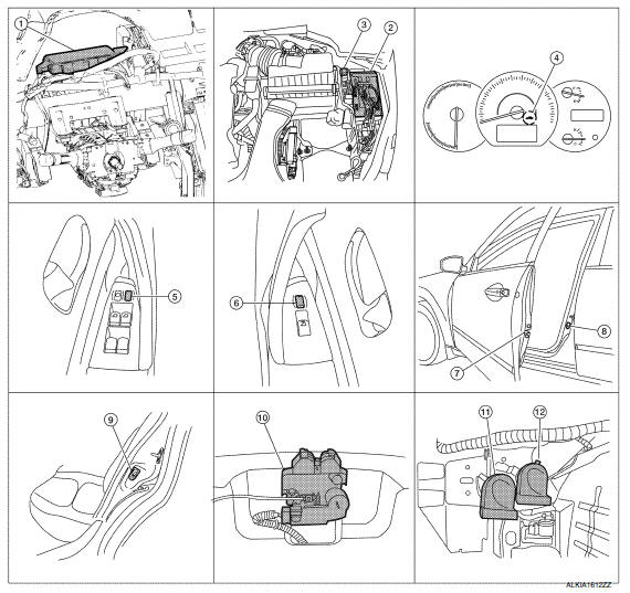
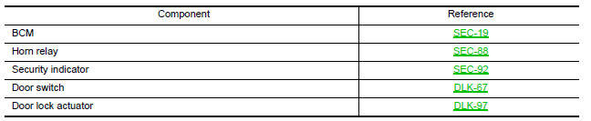
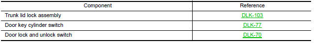
Component Parts Location
-
BCM M16, M17, M18, M19, M21 (view with instrument panel removed)
-
IPDM E/R E17, E18
-
Horn relay H-1
-
Security indicator lamp
-
Main power window and door lock/unlock switch D7, D8
-
Power window and door lock/unlock switch RH D105
-
Front door lock assembly LH D10
-
Front door switch LH B8 RH B108
-
Rear door switch LH B18 RH B116
-
Trunk lamp switch and trunk release solenoid T7
-
Horn (low) E215 (view with front fender protector LH removed)
-
Horn (high) E216
Component Description
 NVIS (NISSAN vehicle immobilizer system-nats)
System Diagram
System Description
INPUT/OUTPUT SIGNAL CHART
SYSTEM DESCRIPTION
The NVIS (NATS) is an anti-theft system. By registering an
Intelligent Key ID into the vehicle, it prevents ...
 Diagnosis system (BCM)
COMMON ITEM
COMMON ITEM : CONSULT Function (BCM - COMMON ITEM)
APPLICATION ITEM
CONSULT performs the following functions via CAN
communication with BCM.
SYSTEM APPLICATION
BCM can perform the ...
Other materials:
U1000 CAN comm circuit
Description
CAN (Controller Area Network) is a serial communication line for real time
application. It is an on-vehicle multiplex communication line with high data
communication speed and excellent error detection ability. Many electronic
control units are equipped on a vehicle and each contr ...
Opening the trunk lid
1. Push the trunk opener request switch A for
more than 1 second while carrying the Intelligent
Key with you. If all doors are already
unlocked, opening the trunk does NOT require
an Intelligent Key to be in range of the
trunk opener request switch or rear of the
vehicle.
2. The trunk w ...
Charging system
System Diagram
System Description
The generator provides DC voltage to operate the vehicle's electrical system
and to keep the battery charged.
The voltage output is controlled by the IC regulator.
Component Description
...
Nissan Maxima Owners Manual
- Illustrated table of contents
- Safety-Seats, seat belts and supplemental restraint system
- Instruments and controls
- Pre-driving checks and adjustments
- Monitor, climate, audio, phone and voice recognition systems
- Starting and driving
- In case of emergency
- Appearance and care
- Do-it-yourself
- Maintenance and schedules
- Technical and consumer information
Nissan Maxima Service and Repair Manual

0.0068