Nissan Maxima Service and Repair Manual: System description
INTELLIGENT KEY SYSTEM/ENGINE START FUNCTION
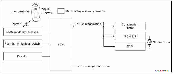
System Diagram
System Description
INPUT/OUTPUT SIGNAL CHART
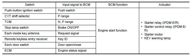
SYSTEM DESCRIPTION
- The engine start function of Intelligent Key system is a system
that makes it possible to start and stop the
engine without removing the key. It verifies the electronic ID using two-way
communications when pressing
the push-button ignition switch while carrying the Intelligent Key, which
operates based on the results of
electronic ID verification for Intelligent Key using two-way communications
between the Intelligent Key and
the vehicle.
NOTE: The driver should carry the Intelligent Key at all times.
- Intelligent Key has 2 IDs [for Intelligent Key and for NVIS (NATS)]. It can perform the door lock/unlock operation and the push-button ignition switch operation when the registered Intelligent Key is carried.
- When the Intelligent Key battery is discharged, it can be used as emergency back-up by inserting the Intelligent Key to the key slot. At that time, perform the NVIS (NATS) ID verification. If it is used when the Intelligent Key is carried, perform the Intelligent Key ID verification.
- When the push-button ignition switch is pressed the ID will be verified. If the ID is successfully verified, starting the engine will be possible.
- If the door lock/unlock operation is performed when the Intelligent Key battery is discharged, all doors lock/ unlock can be performed by operating the driver door key cylinder using the mechanical key set in the Intelligent Key.
- Intelligent Key system can register up to 4 keys (Including the
standard Intelligent Key) on request from the
owner.
NOTE:
- Refer to DLK-24, "INTELLIGENT KEY : System Description" for any functions other than engine start function of Intelligent Key system.
PRECAUTIONS FOR INTELLIGENT KEY SYSTEM
- In the Intelligent Key system of model A35, the transponder [the chip for NVIS (NATS) ID verification] is integrated into the Intelligent Key. (For the conventional models, it is integrated into the mechanical key.) Therefore, the mechanical key cannot perform the ID verification, and thus it cannot start the engine. Instead, the NVIS (NATS) ID verification can be performed by inserting the Intelligent Key into the key slot, and then it can start the engine.
OPERATION WHEN INTELLIGENT KEY IS CARRIED
- When the push-button ignition switch is pressed and brake pedal is depressed, the BCM signals the inside key antenna and transmits the request signal to the Intelligent Key.
- The Intelligent Key sends the request signal and transmits the Intelligent Key ID signal to the BCM via the remote keyless entry receiver.
- The BCM receives the Intelligent Key ID signal and verifies it with the registered ID.
- BCM turns ACC relay ON and transmits the ignition power supply ON signal to IPDM E/R.
- IPDM E/R turns the ignition relay ON and starts the ignition power supply.
- BCM confirms that the shift position is P or N.
- BCM transmits the starter request signal via CAN communication to IPDM E/R and turns the starter relay in IPDM E/R ON if BCM judges that the engine start condition is satisfied.
- IPDM E/R turns the starter control relay ON when receiving the starter request signal.
- Battery power is supplied through the starter relay and the
starter control relay to operate the starter motor
and to start the cranking.
CAUTION: If a malfunction is detected in the Intelligent Key system, the "KEY" warning lamp in the combination meter illuminates. At that time, the engine cannot be started.
- When BCM received feedback signal from ECM acknowledging the engine has been initiated, the BCM transmits a stop signal to IPDM E/R and stops the cranking by turning OFF the starter motor relay. (If the engine initiating has failed, the cranking will stop automatically within 5 seconds.) CAUTION: When the Intelligent Key is carried outside of the vehicle (inside key antenna detection area) with the power supply in ACC or ON position, even if the engine start condition* is satisfied, the engine cannot be started.
*: For the engine start condition, refer to "PUSH-BUTTON IGNITION SWITCH OPERATION PROCEDURE".
OPERATION RANGE
Engine can be started when Intelligent Key is inside the vehicle. However, sometimes engine might not start when Intelligent Key is on instrument panel or in glove box.
OPERATION WHEN KEY SLOT IS USED
When the Intelligent Key battery is discharged, it performs the NVIS (NATS) ID verification between the integrated transponder and BCM by inserting the Intelligent Key into the key slot, and then the engine can be started.
For details relating to starting the engine using key slot, refer to SEC-10, "System Description".
BATTERY SAVER SYSTEM
When all the following conditions are met for 60 minutes, the battery saver system will cut off the power supply to prevent battery discharge.
- The ignition switch is in the ACC position
- All doors are closed
- CVT selector lever is in the P position
- No Intelligent Key failures (Intelligent Key warning indicator is not ON)
Reset Condition of Battery Saver System
In order to prevent the battery from discharging, the battery saver system will cut off the power supply when all doors are closed, the selector lever is in P position and the ignition switch is left in ACC position for 1 hour. If any of the following conditions are met, the battery saver system is released:
- Opening any door
- Operating with request switch on door lock
- - Operating with Intelligent Key on door lock
Press push-button ignition switch and ignition switch will change to ACC position from OFF position.
PUSH-BUTTON IGNITION SWITCH OPERATION PROCEDURE
The power supply position changing operation can be performed with the following operations:
NOTE:
- When an Intelligent Key is within the detection area of inside key antenna or when it is inserted to the key slot, it is equivalent to the operations below.
- When starting the engine, the BCM monitors under the
engine start conditions.
- Brake pedal operating condition
- CVT selector lever position
- Vehicle speed
- Engine status
- Unless each start condition is fulfilled, the engine will not respond regardless of how many times the engine switch is pressed. At that time, illumination repeats the position in the order of LOCK→ACC→ON→OFF.
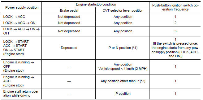
*1: When the CVT selector lever position is N position, the engine start condition is different according to the vehicle speed.
- At vehicle speed of 4 km/h (2 MPH) or less, the engine can start only when the brake pedal is depressed.
- At vehicle speed of 4 km/h (2 MPH) or more, the engine can start even if the brake pedal is not depressed. (It is the same as "Engine stall return operation while driving".)
*2: When the CVT selector lever position is in any position other than P position and when the vehicle speed is 5 km/h (3 MPH) or more, the engine stop condition is different.
- Press and hold the push-button ignition switch for 2 seconds or more. (When the push-button ignition switch is pressed for too short a time, the operation may be invalid, so properly press and hold to prevent an incorrect operation.)
- Press the push-button ignition switch 3 times or more within 1.5 seconds. (Emergency stop operation)
Component Parts Location
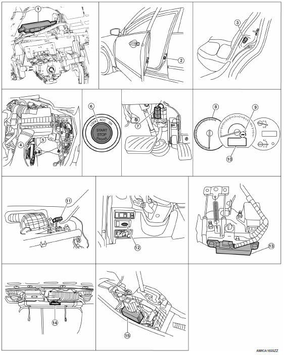
- BCM M16, M17, M18, M19, M21 (view with instrument panel removed)
- Front door switch LH B8 RH B108
- Rear door switch LH B18 RH B116
- TCM F15
- ECM E10
- Push button ignition switch M38
- Stop lamp switch E38 (view with lower driver instrument panel removed)
- Combination meter M24
- Security indicator lamp
- Information display
- Remote keyless entry receiver M27 (view with instrument panel removed)
- Key slot M40
- Front console antenna M41 (view with center console removed)
- Rear parcel shelf antenna B29
- CVT shift selector M78
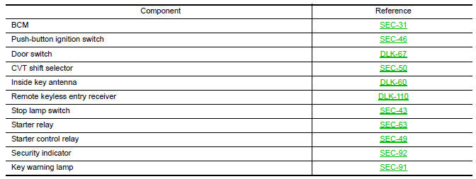
Component Description
 Inspection and adjustment
ECM RE-COMMUNICATING FUNCTION
ECM RE-COMMUNICATING FUNCTION : Description
the ECM has been replaced with a new one (*1).
*1: New one means an ECM which has never been energized on-board.
(In t ...
 NVIS (NISSAN vehicle immobilizer system-nats)
System Diagram
System Description
INPUT/OUTPUT SIGNAL CHART
SYSTEM DESCRIPTION
The NVIS (NATS) is an anti-theft system. By registering an
Intelligent Key ID into the vehicle, it prevents ...
Other materials:
Power steering oil pump
Inspection
CAUTION: Make sure that belt tension is
normal before starting the following procedure.
Connect the Tool between oil pump discharge connector and
high-pressure hose. Bleed air from the hydraulic circuit while opening
the shut-off valve fully. Refer to ST-12, "Inspection".
...
Trunk lid opener
Wiring Diagram
...
Microphone
Removal and Installation
REMOVAL
Remove the front room/map lamp assembly. Refer to INL-84, "Removal
and Installation".
Detach the microphone connector (A).
Remove the front room/map lamp covers (1), then remove the map lamp
assembly cover (2).
Release the microphone tab ...
Nissan Maxima Owners Manual
- Illustrated table of contents
- Safety-Seats, seat belts and supplemental restraint system
- Instruments and controls
- Pre-driving checks and adjustments
- Monitor, climate, audio, phone and voice recognition systems
- Starting and driving
- In case of emergency
- Appearance and care
- Do-it-yourself
- Maintenance and schedules
- Technical and consumer information
Nissan Maxima Service and Repair Manual

0.0056