
Nissan Maxima Service and Repair Manual: Rear door finisher
Exploded View
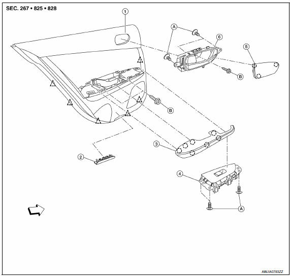
- Rear door finisher
- Step lamp
- Armrest finisher
- Rear power window switch finisher
- Inside release handle escutcheon
- Inside release handle
- Flat head screws
- Screw
 Clip
Clip
 Pawl
Pawl
 Front
Front
Removal and Installation
CAUTION: Wrap the tip of a suitable tool with a cloth when removing metal clips from finishers.
REMOVAL
- Remove the step lamp. Refer to INL-84, "Removal and Installation".
- Release the pawls at the rear edge and remove the inside release handle escutcheon, then remove the screw.
- Remove the rear door armrest.
- Lift up to release the rear door armrest pawls.
- Disconnect the harness connector from the rear power window switch.
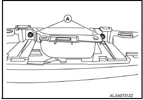
- Remove the rear door finisher screws (A).
- Release the rear door finisher clips using a suitable tool (A)
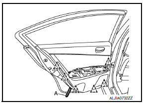
 : Clip
- Disconnect inside handle cable and the door lock cable from the back of rear door finisher.
- Remove the rear door finisher.
INSTALLATION
Installation is in the reverse order of removal.
 Front door finisher
Exploded View
Mirror cover
Front door finisher
Step lamp
Arm rest finisher
Main power window and door lock/ unlock switch finisher
Front door grip cover
Seat memory switch (if equ ...
 Body side trim
Exploded View
Front pillar finisher
Dash side lower finisher
Front kicking plate
Front sill cover
Center pillar lower finisher
Rear sill cover
Rear kicking plate
Rear body sid ...
Other materials:
Maintenance schedules
To help ensure smooth, safe and economical
driving, NISSAN provides two maintenance
schedules that may be used, depending upon the
conditions in which you usually drive. These
schedules contain both distance and time intervals,
up to 120,000 miles
(192,000 km)/144 months. For most people, the
...
Symptom diagnosis
SQUEAK AND RATTLE TROUBLE DIAGNOSES
Work Flow
CUSTOMER INTERVIEW
Interview the customer if possible, to determine the conditions that exist
when the noise occurs. Use the Diagnostic Worksheet during the interview to
document the facts and conditions when the noise occurs and any customer' ...
P0139, P0159 HO2S2
Description
The heated oxygen sensor 2, after three way catalyst (manifold),
monitors the oxygen level in the exhaust gas on each bank.
Even if switching characteristics of the air fuel ratio (A/F) sensor 1
are shifted, the air-fuel ratio is controlled to stoichiometric, by the signal
...
Nissan Maxima Owners Manual
- Illustrated table of contents
- Safety-Seats, seat belts and supplemental restraint system
- Instruments and controls
- Pre-driving checks and adjustments
- Monitor, climate, audio, phone and voice recognition systems
- Starting and driving
- In case of emergency
- Appearance and care
- Do-it-yourself
- Maintenance and schedules
- Technical and consumer information
Nissan Maxima Service and Repair Manual

0.0143