Nissan Maxima Service and Repair Manual: B1017 - B1022 occupant classification system
Description
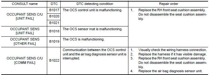
DTC B1017 - B1022 OCCUPANT CLASSIFICATION SYSTEM (OCS)
The occupant classification system control unit is wired to the air bag
diagnosis sensor unit. The air bag diagnosis
sensor unit will monitor the
occupant classification system for control unit and sensor mat failures and
interruptions in communication between the OCS control unit and the air bag
diagnosis sensor unit.
PART LOCATION
DTC Logic
DTC DETECTION LOGIC
With CONSULT
DTC CONFIRMATION PROCEDURE (With CONSULT)
1.CHECK SELF-DIAG RESULT
- . Turn ignition switch ON.
- Check for DTC using CONSULT
2.ERASE SELF-DIAG RESULT
Erase the DTC using CONSULT.
DTC CONFIRMATION PROCEDURE (Without CONSULT)
1.CHECK SELF-DIAG RESULT
- Turn ignition switch ON.
- Check the air bag warning lamp status. Refer to SRC-14, "Trouble Diagnosis without CONSULT".
NOTE:
SRS will not enter diagnosis mode if
no malfunction is detected in user mode.
Diagnosis Procedure
1.HARNESS CONNECTOR
Visually inspect all applicable harness connectors for the following:
- Visible damage to connector or terminal
- Loose terminal
- Poor connection
NOTE:
All harness connectors should be
inspected from the air bag diagnosis sensor unit to the end component
(including any in-line connectors).
2.CONFIRM DTC
- Reconnect all harness connectors.
- Turn ignition switch ON.
- Check for DTC using CONSULT.
3.WIRING HARNESS
Check the wiring harness for visible damage.
NOTE:
The entire wiring harness should be
inspected from the air bag diagnosis sensor unit to the end component
(including any in-line connectors).
4.CONFIRM DTC
- Reconnect all harness connectors.
- Turn ignition switch ON.
- Check for DTC using CONSULT.
5.AIR BAG DIAGNOSIS SENSOR UNIT
- Replace the air bag diagnosis sensor unit. Refer to SR-31, "Removal and Installation".
- Turn ignition switch ON.
- Check for DTC using CONSULT.
6.RH FRONT SEAT CUSHION ASSEMBLY
- Replace the RH front seat cushion assembly. Refer to SE-68,
"Removal and Installation" (with climate
controlled seats) or SE-126, "Removal and Installation" (without climate controlled seats). - Turn ignition switch ON.
- Check for DTC using CONSULT
7.RELATED HARNESS
Replace the related harness.
 B1023 passenger air bag off indicator
Description
DTC B1023 FRONT PASSENGER AIR BAG OFF INDICATOR
The front passenger air bag off indicator is wired to the air bag diagnosis
sensor unit. The air bag diagnosissensor unit monitors the f ...
 B1209 - B1210 collision detection
Description
DTC B1209 - B1210 COLLISION DETECTION
The air bag diagnosis sensor unit will set this DTC if it has detected a
collision which has resulted in a frontalor side deployment of one or mor ...
Other materials:
Operating range
The Intelligent Key functions can only be used
when the Intelligent Key is within the specified
operating range from the request switch 1 .
NOTE:
If all doors are already unlocked, opening
the trunk does NOT require an Intelligent
Key to be in range of the trunk request
switch or rear of ...
Squeak and rattle trouble diagnoses
Work Flow
CUSTOMER INTERVIEW
Interview the customer if possible, to determine the conditions that exist
when the noise occurs. Use the Diagnostic
Worksheet during the interview to document the facts and conditions when the
noise occurs and any
customer's comments; refer to SE-56, "Diagno ...
ECU diagnosis information
A/C AUTO AMP
Reference Value
VALUES ON THE DIAGNOSIS TOOL
CONSULT MONITOR ITEM
A/C AUTO AMP. HARNESS CONNECTOR TERMINAL LAYOUT
TERMINALS AND REFERENCE VALUES FOR A/C AUTO AMP.
Fail-Safe
FAIL-SAFE FUNCTION
If a communication error exists between the A/C auto amp., the AV
...
Nissan Maxima Owners Manual
- Illustrated table of contents
- Safety-Seats, seat belts and supplemental restraint system
- Instruments and controls
- Pre-driving checks and adjustments
- Monitor, climate, audio, phone and voice recognition systems
- Starting and driving
- In case of emergency
- Appearance and care
- Do-it-yourself
- Maintenance and schedules
- Technical and consumer information
Nissan Maxima Service and Repair Manual

0.0078