Nissan Maxima Service and Repair Manual: P0461 fuel level sensor
Description
The fuel level sensor is mounted in the fuel level sensor unit.
The sensor detects a fuel level in the fuel tank and transmits a signal to the combination meter. The combination meter sends the fuel level sensor signal to the ECM via the CAN communication line.
It consists of two parts, one is mechanical float and the other is variable resistor. Fuel level sensor output voltage changes depending on the movement of the fuel mechanical float.
DTC Logic
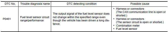
DTC DETECTION LOGIC
NOTE:
- If DTC P0461 is displayed with DTC UXXXX, first perform the
trouble diagnosis for DTC UXXXX.
Refer to EC-161, "DTC Logic".
- If DTC P0461 is displayed with DTC P0607, first perform the trouble diagnosis for DTC P0607. Refer to EC-393, "DTC Logic".
Driving long distances naturally affect fuel gauge level.
This diagnosis detects the fuel gauge malfunction of the gauge not moving even after a long distance has been driven.
DTC CONFIRMATION PROCEDURE
1.PERFORM COMPONENT FUNCTION CHECK
Perform component function check. Refer to EC-374, "Component Function Check".
Use component function check to check the overall function of the fuel level sensor. During this check, a 1st trip DTC might not be confirmed.
Component Function Check
1.PRECONDITIONING
WARNING: When performing the following procedure, always observe the handling of the fuel. Refer to FL-6, "Removal and Installation". TESTING CONDITION: Before starting component function check, preparation of draining fuel and refilling fuel is required.
2.PERFORM COMPONENT FUNCTION CHECK
With CONSULT
NOTE: Start from step 10, if it is possible to confirm that the fuel cannot be drained by 30 (7-7/8 US gal, 6-5/ 8 Imp gal) in advance.
- Prepare a fuel container and a spare hose.
- Release fuel pressure from fuel line, refer to EC-594, "Inspection".
- Remove the fuel feed hose on the fuel level sensor unit. Refer to FL-6, "Removal and Installation".
- Connect a spare fuel hose where the fuel feed hose was removed.
- Turn ignition switch OFF and wait at least 10 seconds then turn ON.
- Select "FUEL LEVEL SE" in "DATA MONITOR" mode with CONSULT.
- Check "FUEL LEVEL SE" output voltage and note it.
- Select "FUEL PUMP RELAY" in "ACTIVE TEST" mode with CONSULT.
- Touch "ON" and drain fuel approximately 30
 (7-7/8 US gal, 6-5/8 Imp gal)
and stop it.
(7-7/8 US gal, 6-5/8 Imp gal)
and stop it. - Check "FUEL LEVEL SE" output voltage and note it.
- Fill fuel into the fuel tank for 30
 (7-7/8 US gal, 6-5/8 Imp
gal).
(7-7/8 US gal, 6-5/8 Imp
gal). - Check "FUEL LEVEL SE" output voltage and note it.
- Confirm whether the voltage changes more than 0.03 V during step 7 to 10 and 10 to 12.
3.PERFORM COMPONENT FUNCTION CHECK
Without CONSULT
NOTE: Start from step 8, if it is possible to confirm that the fuel cannot be drained by 30 (7-7/8 US gal, 6-5/8 Imp gal) in advance.
- Prepare a fuel container and a spare hose.
- Release fuel pressure from fuel line. Refer to EC-594, "Inspection".
- Remove the fuel feed hose on the fuel level sensor unit. Refer to FL-6, "Removal and Installation".
- Connect a spare fuel hose where the fuel feed hose was removed.
- Turn ignition switch ON.
- Drain fuel by 30
 (7-7/8 US gal, 6-5/8 Imp gal) from the fuel tank using proper equipment.
 - Confirm that the fuel gauge indication varies.
- Fill fuel into the fuel tank for 30
 (7-7/8 US gal, 6-5/8 Imp
gal).
(7-7/8 US gal, 6-5/8 Imp
gal). - Confirm that the fuel gauge indication varies.
Diagnosis Procedure
1.CHECK COMBINATION METER FUNCTION
2.CHECK INTERMITTENT INCIDENT
 P0460 fuel level sensor
Description
The fuel level sensor is mounted in the fuel level sensor unit.
The sensor detects a fuel level in the fuel tank and transmits a signal to the
combination meter. The combination
me ...
 P0462, P0463 fuel level sensor
Description
The fuel level sensor is mounted in the fuel level sensor unit.
The sensor detects a fuel level in the fuel tank and transmits a signal to the
combination meter. The combination
me ...
Other materials:
P0420, P0430 three way catalyst function
DTC Logic
DTC DETECTION LOGIC
The ECM monitors the switching frequency ratio of air fuel ratio (A/F)
sensor 1 and heated oxygen sensor 2.
A three way catalyst (manifold) with high oxygen storage capacity
will indicate a low switching frequency of heated oxygen sensor 2.
As oxygen sto ...
P0131, P0151 A/F sensor 1
Description
The air fuel ratio (A/F) sensor 1 is a planar one-cell limit current sensor.
The sensor element of the A/F sensor 1 is composed an electrode
layer, which transports ions. It has a heater in the element.
The sensor is capable of precise measurement = 1, but also in the
lean ...
Unit removal and installation
TRANSAXLE ASSEMBLY
Exploded View
Air breather hose
CVT fluid level gauge
CVT fluid charging pipe
O-ring
Copper sealing washer
Fluid cooler tube
Transaxle assembly
A. Refer to INSTALLATION.
...
Nissan Maxima Owners Manual
- Illustrated table of contents
- Safety-Seats, seat belts and supplemental restraint system
- Instruments and controls
- Pre-driving checks and adjustments
- Monitor, climate, audio, phone and voice recognition systems
- Starting and driving
- In case of emergency
- Appearance and care
- Do-it-yourself
- Maintenance and schedules
- Technical and consumer information
Nissan Maxima Service and Repair Manual

0.0057