Nissan Maxima Service and Repair Manual: ECM branch line circuit
Diagnosis Procedure
1.CHECK CONNECTOR
-
Turn the ignition switch OFF.
-
Disconnect the battery cable from the negative terminal.
-
Check the following terminals and connectors for damage, bend and loose connection (unit side and connector side).
Models without automatic drive positioner
-
ECM
-
Harness connector E30
-
Harness connector M1
Models with automatic drive positioner
-
ECM
-
Harness connector E29
-
Harness connector B10
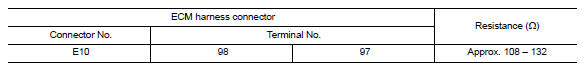
2.CHECK HARNESS FOR OPEN CIRCUIT
-
Disconnect the connector of ECM.
-
Check the resistance between the ECM harness connector terminals.
3.CHECK POWER SUPPLY AND GROUND CIRCUIT
Check the power supply and the ground circuit of the ECM. Refer to EC-157, "Diagnosis Procedure".
Is the inspection result normal?
 Main line between A-bag and ABS circuit
Diagnosis Procedure
1.CHECK CONNECTOR
Turn the ignition switch OFF.
Disconnect the battery cable from the negative
terminal.
Check the following terminals ...
 ADP branch line circuit
Diagnosis Procedure
1.CHECK CONNECTOR
Turn the ignition switch OFF.
Disconnect the battery cable from the negative
terminal.
Check the following terminals ...
Other materials:
Removal and installation
HORN
Removal and Installation
REMOVAL
Remove the engine under cover. Refer to EXT-16, "Removal and
Installation".
Position aside the front fender protector (LH). Refer to EXT-24,
"Removal and Installation".
Disconnect the harness connectors (A) from the horns.
Remove the horn brack ...
Headlamp (HI) circuit
Description
The IPDM E/R (intelligent power distribution module engine room) controls the
headlamp high relay based on inputs from the BCM over the CAN communication
lines. When the headlamp high relay is energized, power flows through fuses
48 and 49, located in the IPDM E/R. Power then flow ...
B2190 nats antenna AMP.
Description
Performs ID verification through BCM and Intelligent Key
when push-button ignition switch is pressed.
Prohibits the start of engine when an unregistered ID of Intelligent Key is
used.
DTC Logic
DTC DETECTION LOGIC
DTC CONFIRMATION PROCEDURE
1.PERFORM DTC CONFIRMATION PROCED ...
Nissan Maxima Owners Manual
- Illustrated table of contents
- Safety-Seats, seat belts and supplemental restraint system
- Instruments and controls
- Pre-driving checks and adjustments
- Monitor, climate, audio, phone and voice recognition systems
- Starting and driving
- In case of emergency
- Appearance and care
- Do-it-yourself
- Maintenance and schedules
- Technical and consumer information
Nissan Maxima Service and Repair Manual

0.0051