Nissan Maxima Service and Repair Manual: Engine control system symptoms
Symptom Table
SYSTEM - BASIC ENGINE CONTROL SYSTEM
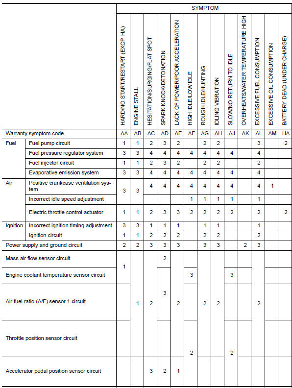
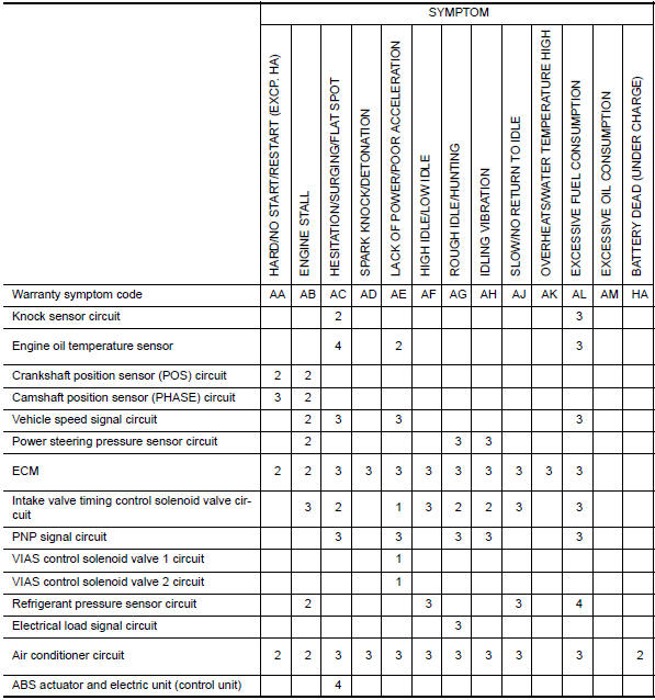
1 - 6: The numbers refer to the order of inspection.
(continued on next page)
SYSTEM - ENGINE MECHANICAL & OTHER
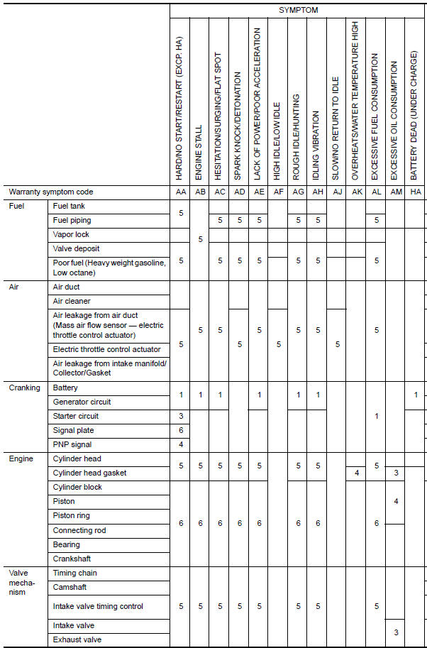
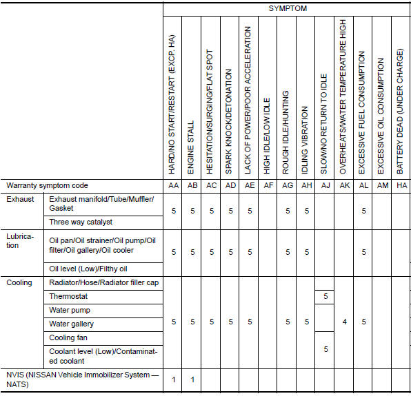
1 - 6: The numbers refer to the order of inspection.

 Normal operating condition
Description
FUEL CUT CONTROL (AT NO LOAD AND HIGH ENGINE SPEED)
If the engine speed is above 2,000 rpm under no load (for example, the
selector lever position is P or N and
engine speed is over ...
Other materials:
ADP branch line circuit
Diagnosis Procedure
1.CHECK CONNECTOR
Turn the ignition switch OFF.
Disconnect the battery cable from the negative terminal.
Check the following terminals and connectors for damage, bend and
loose connection (unit side and connector
side).
Driver seat control unit
Harness connec ...
Vehicle Dynamic Control (VDC) system
The VDC system uses various sensors to monitor
driver inputs and vehicle motion. Under certain
driving conditions, the VDC system helps to perform
the following functions:
Controls brake pressure to reduce wheel
slip on one slipping drive wheel so power is
transferred to a non slipping dr ...
Low tire pressure warning
If the vehicle is being driven with low tire
pressure, the warning light will illuminate.
A "Tire Pressure Low - Add Air" warning
also appears in the vehicle information display.
When the low tire pressure warning light
illuminates, you should stop and adjust the
tire pressure of all four ...
Nissan Maxima Owners Manual
- Illustrated table of contents
- Safety-Seats, seat belts and supplemental restraint system
- Instruments and controls
- Pre-driving checks and adjustments
- Monitor, climate, audio, phone and voice recognition systems
- Starting and driving
- In case of emergency
- Appearance and care
- Do-it-yourself
- Maintenance and schedules
- Technical and consumer information
Nissan Maxima Service and Repair Manual

0.006