Nissan Maxima Service and Repair Manual: Main line between A-bag and ABS circuit
Diagnosis Procedure
1.CHECK CONNECTOR
-
Turn the ignition switch OFF.
-
Disconnect the battery cable from the negative terminal.
-
Check the following terminals and connectors for damage, bend and loose connection (connector side and harness side).
-
Harness connector M1
-
Harness connector E30
-
2.CHECK HARNESS CONTINUITY (OPEN CIRCUIT)
-
Disconnect the following harness connectors.
-
A/C auto amp.
-
Harness connectors M1 and E30
-
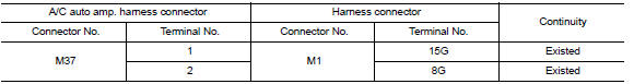
-
Check the continuity between the A/C auto amp. harness connector and the harness connector.
3.CHECK HARNESS CONTINUITY (OPEN CIRCUIT)
-
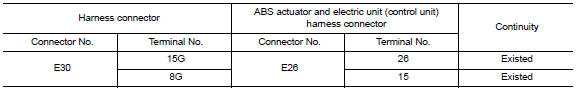
Disconnect the connector of ABS actuator and electric unit (control unit).
-
Check the continuity between the harness connector and the ABS actuator and electric unit (control unit) harness connector.
 Main line between HVAC and A-bag circuit
Diagnosis Procedure
1.CHECK HARNESS CONTINUITY (OPEN CIRCUIT)
Turn the ignition switch OFF.
Disconnect the battery cable from the negative
terminal.
Discon ...
 ECM branch line circuit
Diagnosis Procedure
1.CHECK CONNECTOR
Turn the ignition switch OFF.
Disconnect the battery cable from the negative
terminal.
Check the following terminals ...
Other materials:
Both side headlamps do not switch to high beam
Description
The headlamps (both sides) do not switch to high beam when the lighting
switch is in the HI or PASS setting.
Diagnosis Procedure
1.COMBINATION SWITCH (LIGHTING AND TURN SIGNAL SWITCH) INSPECTION
Check the combination switch (lighting and turn signal switch).
2.CHECK HEADLAMP (HI) ...
Power window main switch
Reference Value
TERMINAL LAYOUT
PHYSICAL VALUES
MAIN POWER WINDOW AND DOOR LOCK/UNLOCK SWITCH
Fail Safe
FAIL-SAFE CONTROL
Switches to fail-safe control when malfunction is detected in encoder signal
that detects up/down speed and
direction of door glass. Switches to fail-safe c ...
P0715 input speed sensor A
Description
The primary speed sensor detects the primary pulley revolution speed and
sends a signal to the TCM.
DTC Logic
DTC DETECTION LOGIC
DTC CONFIRMATION PROCEDURE
CAUTION:
Always drive vehicle at a safe speed.
NOTE:
Immediately after performing any "DTC CONFIRMATION PROCEDURE", a ...
Nissan Maxima Owners Manual
- Illustrated table of contents
- Safety-Seats, seat belts and supplemental restraint system
- Instruments and controls
- Pre-driving checks and adjustments
- Monitor, climate, audio, phone and voice recognition systems
- Starting and driving
- In case of emergency
- Appearance and care
- Do-it-yourself
- Maintenance and schedules
- Technical and consumer information
Nissan Maxima Service and Repair Manual

0.0059