Nissan Maxima Service and Repair Manual: P1740 select solenoid
Description
-
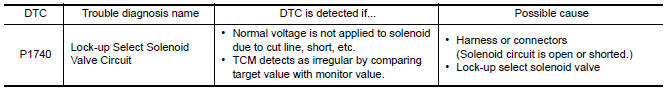
The lock-up select solenoid valve controls lock-up clutch pressure or forward clutch pressure (reverse brake pressure).
-
When controlling lock-up clutch, the valve is turned OFF. When controlling forward clutch, it is turned ON.
DTC Logic
DTC DETECTION LOGIC
DTC CONFIRMATION PROCEDURE
CAUTION: Always drive vehicle at a safe speed.
NOTE: Immediately after performing any "DTC CONFIRMATION PROCEDURE", always turn ignition switch OFF.
Then wait at least 10 seconds before performing the next test.
1.CHECK DTC DETECTION
 With CONSULT
-
Turn ignition switch ON.
-
Select "Data Monitor" in "TRANSMISSION".
-
Start engine and maintain the following conditions for at least 5 consecutive seconds.
RANGE : "D" and "N" position (At each time, wait for 5 seconds.)
 With GST
Follow the procedure "With CONSULT".
Diagnosis Procedure
Regarding Wiring Diagram information, refer to TM-126, "Wiring Diagram".
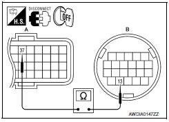
1.CHECK LOCK-UP SELECT SOLENOID VALVE CIRCUIT
-
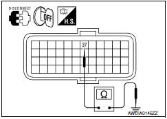
Turn ignition switch OFF.
-
Disconnect TCM connector.
-
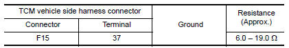
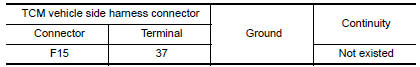
Check resistance between TCM vehicle side harness connector terminal and ground.
2.CHECK HARNESS BETWEEN TCM AND CVT UNIT (LOCK-UP SELECT SOLENOID VALVE) (PART 1)
-
Disconnect CVT unit connector.
-
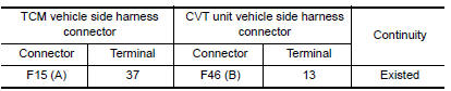
Check continuity between TCM vehicle side harness connector terminal and CVT unit vehicle side harness connector terminal.
3.CHECK HARNESS BETWEEN TCM AND CVT UNIT (LOCK-UP SELECT SOLENOID VALVE) (PART 2)
Check continuity between TCM vehicle side harness connector terminal and ground.
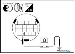
4.CHECK LOCK-UP SELECT SOLENOID VALVE
Check lock-up select solenoid valve. Refer to TM-107, "Component Inspection (Lock-up Select Solenoid Valve)".
5.DETECT MALFUNCTIONING ITEMS
Check TCM connector pin terminals for damage or loose connection with harness connector.
Component Inspection (Lock-up Select Solenoid Valve)
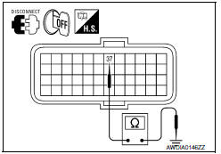
1.CHECK LOCK-UP SELECT SOLENOID VALVE
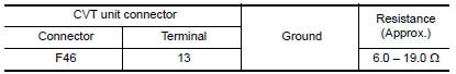
Check resistance between CVT unit connector terminal and ground.
 P1726 throttle control signal
Description
The electric throttle control actuator consists of
throttle control motor, accelerator pedal position sensor, throttle
position sensor, etc. The actuator sends a signal to the ECM, an ...
 P1745 line pressure control
Description
The line pressure solenoid valve regulates the oil pump
discharge pressure to suit the driving condition in
response to a signal sent from the TCM.
DTC Logic
DTC DETECTION LOGIC
...
Other materials:
Unfastening the seat belts
To unfasten the seat belt, press the button on the
buckle 1 . The seat belt automatically retracts.
Checking seat belt operation
Seat belt retractors are designed to lock seat belt
movement by two separate methods:
When the seat belt is pulled quickly from the
retractor
When the vehi ...
Diagnosis system (AV control unit)
Diagnosis Description
MULTIFUNCTION SWITCH AND PRESET SWITCH SELF-DIAGNOSIS FUNCTION
The ON/OFF operation (continuity) of each switch in the multifunction switch
and preset switch can be checked.
Self-Diagnosis Mode
Press the BACK switch and the
switch of the 8-direction switches with ...
B210C starter control relay
DTC Logic
DTC DETECTION LOGIC
NOTE:
If DTC B210C is displayed with DTC
U1000, first perform the trouble diagnosis for DTC U1000. Refer to
SEC-29, "DTC Logic".
If DTC B210C is displayed with DTC
U1010, first perform the trouble diagnosis for DTC U1010. Refer to
SEC-30, "D ...
Nissan Maxima Owners Manual
- Illustrated table of contents
- Safety-Seats, seat belts and supplemental restraint system
- Instruments and controls
- Pre-driving checks and adjustments
- Monitor, climate, audio, phone and voice recognition systems
- Starting and driving
- In case of emergency
- Appearance and care
- Do-it-yourself
- Maintenance and schedules
- Technical and consumer information
Nissan Maxima Service and Repair Manual

0.006