Nissan Maxima Service and Repair Manual: Wiring diagram
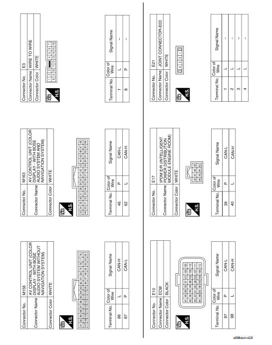
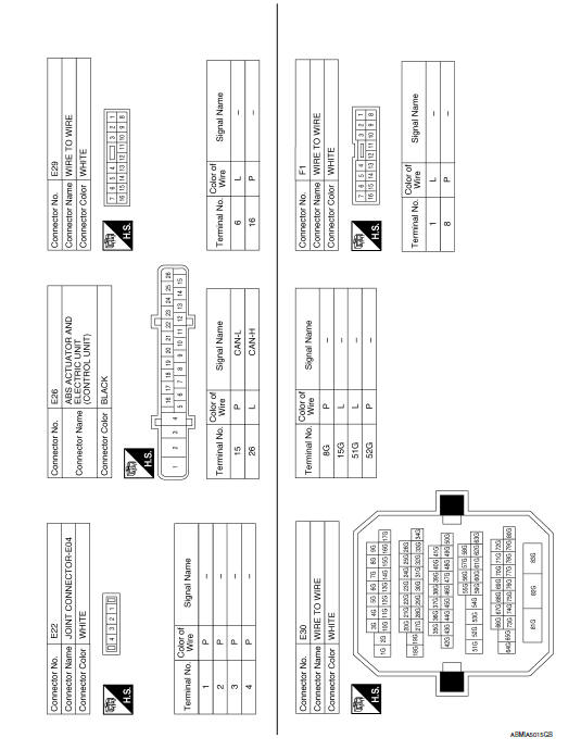
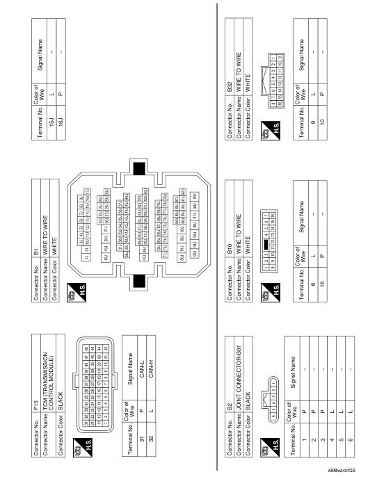
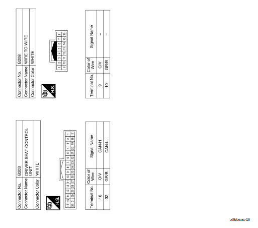
CAN SYSTEM
Wiring Diagram
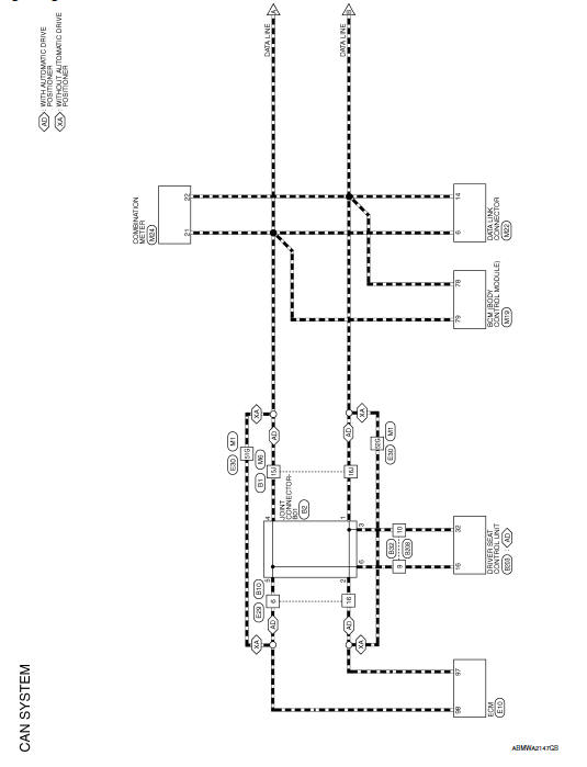
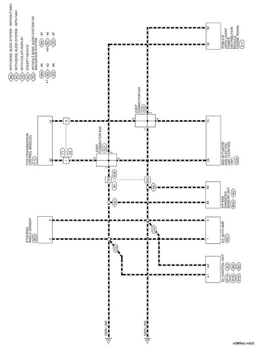
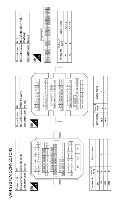
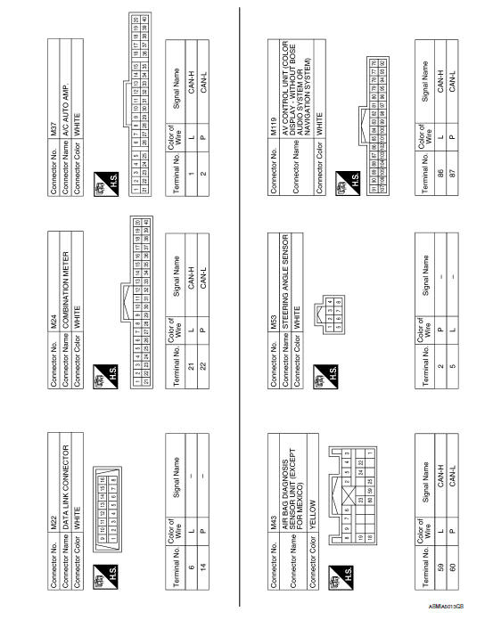
 System description
CAN COMMUNICATION SYSTEM
CAN System Specification Chart
Determine CAN system type from the following specification chart.
NOTE:
Refer to LAN-15, "Trouble Diagnosis Procedure" for how to use CAN
...

Other materials:
Power steering fluid
Check the fluid level in the reservoir.
The fluid level should be checked when the fluid
is cold at fluid temperatures of 32 to 86ºF (0 to
30ºC). The fluid level can be checked with the
level gauge which is attached to the cap. To
check the fluid level, remove the cap. The fluid ...
DTC/circuit diagnosis
SUNSHADE
Component Parts Location
Rear sunshade unit B22 (View with the rear parcel shelf finisher
removed)
Rear sunshade switch M308
Reference Value
...
Precaution
PRECAUTIONS
Precaution for Supplemental Restraint System (SRS) "AIR BAG" and "SEAT BELT
PRE-TENSIONER"
The Supplemental Restraint System such as "AIR BAG" and "SEAT BELT
PRE-TENSIONER", used along
with a front seat belt, helps to reduce the risk or severity of injury to the
driver and fron ...
Nissan Maxima Owners Manual
- Illustrated table of contents
- Safety-Seats, seat belts and supplemental restraint system
- Instruments and controls
- Pre-driving checks and adjustments
- Monitor, climate, audio, phone and voice recognition systems
- Starting and driving
- In case of emergency
- Appearance and care
- Do-it-yourself
- Maintenance and schedules
- Technical and consumer information
Nissan Maxima Service and Repair Manual

0.0069