Nissan Maxima Service and Repair Manual: System description
CAN COMMUNICATION SYSTEM
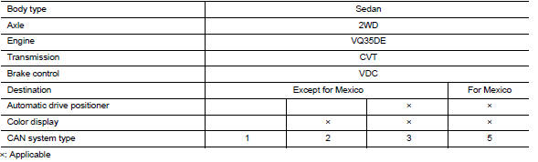
CAN System Specification Chart
Determine CAN system type from the following specification chart.
NOTE:
Refer to LAN-15, "Trouble Diagnosis Procedure" for how to use CAN system specification chart.
VEHICLE EQUIPMENT IDENTIFICATION INFORMATION
NOTE:
Check CAN system type from the vehicle shape and equipment.
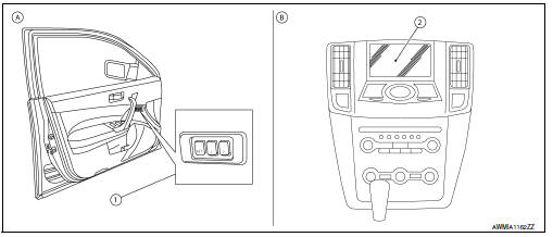
1. Seat memory switches
A. With automatic drive positioner
2. Color display
B. With color display
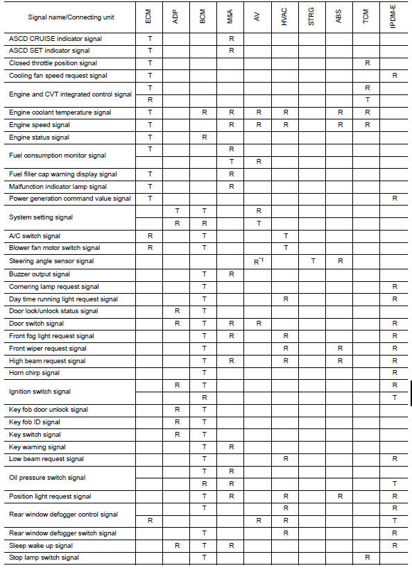
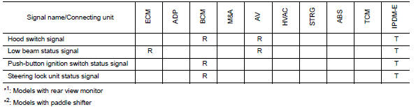
CAN Communication Signal Chart
Refer to LAN-14, "How to Use CAN Communication Signal Chart" for how to use CAN communication signal chart.
NOTE:
Refer to LAN-20, "Abbreviation List" for the abbreviations of the connecting units.
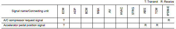
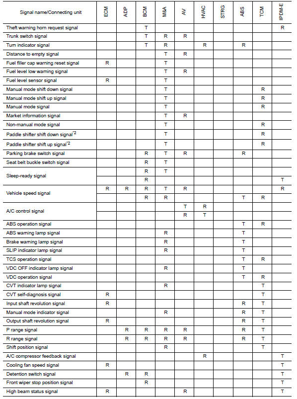
NOTE:
CAN data of the air bag diagnosis sensor unit is not used by usual service work, thus it is omitted.
 Basic inspection
DIAGNOSIS AND REPAIR WORKFLOW
Interview Sheet
...
 Wiring diagram
CAN SYSTEM
Wiring Diagram
...
Other materials:
Tel antenna
Removal and Installation
REMOVAL
Disconnect the battery negative terminal. Refer to PG-68, "Removal
and Installation (Battery Tray)".
Remove the rear parcel shelf finisher. Refer to INT-28, "Removal and
Installation".
Remove the Bluetooth antenna screw (A).
Detach the Bluetooth a ...
P1564 ASCD steering switch
Description
ASCD steering switch has variant values of electrical resistance for each
button. ECM reads voltage variation
of switch, and determines which button is operated.
Refer to EC-68, "System Diagram" for the ASCD function.
DTC Logic
DTC DETECTION LOGIC
NOTE:
If DTC P156 ...
Ground
Ground Distribution
MAIN HARNESS
ENGINE ROOM HARNESS
FRONT END MODULE HARNESS
ENGINE CONTROL HARNESS
BODY HARNESS
BODY NO. 2 HARNESS
...
Nissan Maxima Owners Manual
- Illustrated table of contents
- Safety-Seats, seat belts and supplemental restraint system
- Instruments and controls
- Pre-driving checks and adjustments
- Monitor, climate, audio, phone and voice recognition systems
- Starting and driving
- In case of emergency
- Appearance and care
- Do-it-yourself
- Maintenance and schedules
- Technical and consumer information
Nissan Maxima Service and Repair Manual

0.0067