Nissan Maxima Service and Repair Manual: Malfunction area chart
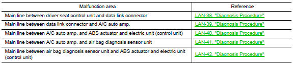
Main Line
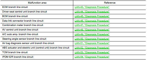
Branch Line
Short Circuit

 Can communication system
Component Parts Location
ABS actuator and electric unit (control
unit) E26
TCM F15
ECM E10
4. IPDM E/R E17
BCM M19
Combination meter M24
...
 Main line between adp and dlc circuit
Diagnosis Procedure
1.CHECK CONNECTOR
Turn the ignition switch OFF.
Disconnect the battery cable from the negative
terminal.
Check the following terminals and connectors for ...
Other materials:
Cleaning exterior
In order to maintain the appearance of your vehicle,
it is important to take proper care of it.
To protect the paint surfaces, please wash your
vehicle as soon as you can:
after a rainfall to prevent possible damage
from acid rain
after driving on coastal roads
when contaminants such ...
Front washer
WASHER TUBE
WASHER TUBE : Layout
Washer nozzle (LH)
Washer nozzle hose (LH)
Washer nozzle (RH)
Washer nozzle hose (RH)
Y-tube connector
Washer tank hose
Washer tank
Tube connectors
Clip
FRONT WASHER NOZZLE
FRONT WASHER NOZZLE : Removal and Installation
REMOVAL
...
Maintenance schedules
To help ensure smooth, safe and economical
driving, NISSAN provides two maintenance
schedules that may be used, depending upon the
conditions in which you usually drive. These
schedules contain both distance and time intervals,
up to 120,000 miles
(192,000 km)/144 months. For most people, the
...
Nissan Maxima Owners Manual
- Illustrated table of contents
- Safety-Seats, seat belts and supplemental restraint system
- Instruments and controls
- Pre-driving checks and adjustments
- Monitor, climate, audio, phone and voice recognition systems
- Starting and driving
- In case of emergency
- Appearance and care
- Do-it-yourself
- Maintenance and schedules
- Technical and consumer information
Nissan Maxima Service and Repair Manual

0.0069