Nissan Maxima Service and Repair Manual: Main line between adp and dlc circuit
Diagnosis Procedure
1.CHECK CONNECTOR
-
Turn the ignition switch OFF.
-
Disconnect the battery cable from the negative terminal.
-
Check the following terminals and connectors for damage, bend and loose connection (connector side and harness side).
-
Harness connector B1
-
Harness connector M6
-
2.CHECK HARNESS CONTINUITY (OPEN CIRCUIT)
-
. Disconnect the following harness connectors.
-
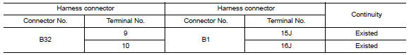
Harness connectors B208 and B32
-
Harness connectors B1 and M6
-
-
Check the continuity between the harness connectors.
3.CHECK HARNESS CONTINUITY (OPEN CIRCUIT)

 Malfunction area chart
Main Line
Branch Line
Short Circuit
...
 Main line between dlc and hvac circuit
Diagnosis Procedure
1.CHECK HARNESS CONTINUITY (OPEN CIRCUIT)
Turn the ignition switch OFF.
Disconnect the battery cable from the negative
terminal.
Disconnect the following ...
Other materials:
Wiring diagram
COLOR DISPLAY
Wiring Diagram - Without BOSE Audio System Without Navigation System
...
Parking brake control
Exploded View
Parking brake pedal
Parking brake switch
Pedal pad
Adjusting nut
Lock plate
Front cable
Rear cable (RH)
Rear cable (LH)
Equalizer
Spring
Pin
Front
Removal and Installation
REMOVAL
Remove rear wheel and tire using power tool. Refer to ...
P0031, P0032, P0051, P0052 A/F sensor 1 heater
Description
SYSTEM DESCRIPTION
The ECM performs ON/OFF duty control of the A/F sensor 1 heater corresponding
to the engine operating
condition to keep the temperature of A/F sensor 1 element within the specified
range.
DTC Logic
DTC DETECTION LOGIC
DTC CONFIRMATION PROCEDURE
1.PR ...
Nissan Maxima Owners Manual
- Illustrated table of contents
- Safety-Seats, seat belts and supplemental restraint system
- Instruments and controls
- Pre-driving checks and adjustments
- Monitor, climate, audio, phone and voice recognition systems
- Starting and driving
- In case of emergency
- Appearance and care
- Do-it-yourself
- Maintenance and schedules
- Technical and consumer information
Nissan Maxima Service and Repair Manual

0.0089