Nissan Maxima Service and Repair Manual: Main line between dlc and hvac circuit
Diagnosis Procedure
1.CHECK HARNESS CONTINUITY (OPEN CIRCUIT)
-
Turn the ignition switch OFF.
-
Disconnect the battery cable from the negative terminal.
-
Disconnect the following harness connectors.
-
ECM
-
A/C auto amp.
-
-
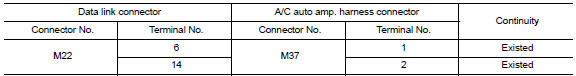
Check the continuity between the data link connector and the A/C auto amp. harness connector.
 Main line between adp and dlc circuit
Diagnosis Procedure
1.CHECK CONNECTOR
Turn the ignition switch OFF.
Disconnect the battery cable from the negative
terminal.
Check the following terminals and connectors for ...
 Main line between hvac and ABS circuit
Diagnosis Procedure
1.CHECK CONNECTOR
Turn the ignition switch OFF.
Disconnect the battery cable from the negative
terminal.
Check the following terminals and connectors for ...
Other materials:
Intake door control system
System Diagram
System Description
The intake doors are automatically controlled by the temperature setting,
ambient temperature, in-vehicle temperature,
intake temperature, amount of sunload and ON/OFF operation of the A/C
compressor.
SYSTEM OPERATION
The intake door control judges inta ...
ABS
System Diagram
System Description
Anti-Lock Braking System is a function that detects wheel revolution
while braking, electronically controls
braking force, and prevents wheel locking during sudden braking. It improves
handling stability and maneuverability
for avoiding obstacle ...
Normal operating condition
Description
FRONT WIPER MOTOR PROTECTION FUNCTION
IPDM E/R may stop the front wiper to protect the front wiper motor
if any obstruction (operation resistance)such as a large amount of snow
is detected during the front wiper operation.
At that time turn OFF the front wiper and remove the ...
Nissan Maxima Owners Manual
- Illustrated table of contents
- Safety-Seats, seat belts and supplemental restraint system
- Instruments and controls
- Pre-driving checks and adjustments
- Monitor, climate, audio, phone and voice recognition systems
- Starting and driving
- In case of emergency
- Appearance and care
- Do-it-yourself
- Maintenance and schedules
- Technical and consumer information
Nissan Maxima Service and Repair Manual

0.0053