Nissan Maxima Service and Repair Manual: Main line between hvac and ABS circuit
Diagnosis Procedure
1.CHECK CONNECTOR
-
Turn the ignition switch OFF.
-
Disconnect the battery cable from the negative terminal.
-
Check the following terminals and connectors for damage, bend and loose connection (connector side and harness side).
-
Harness connector M1
-
Harness connector E30
-
2.CHECK HARNESS CONTINUITY (OPEN CIRCUIT)
-
Disconnect the following harness connectors.
-
A/C auto amp.
-
Harness connectors M1 and E30
-
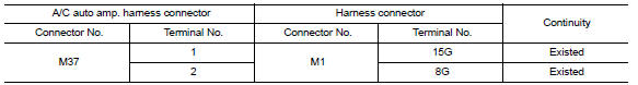
-
Check the continuity between the A/C auto amp. harness connector and the harness connector.
3.CHECK HARNESS CONTINUITY (OPEN CIRCUIT)
-
Disconnect the connector of ABS actuator and electric unit (control unit).
-
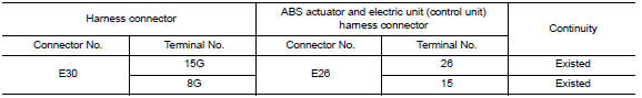
Check the continuity between the harness connector and the ABS actuator and electric unit (control unit) harness connector.
 Main line between dlc and hvac circuit
Diagnosis Procedure
1.CHECK HARNESS CONTINUITY (OPEN CIRCUIT)
Turn the ignition switch OFF.
Disconnect the battery cable from the negative
terminal.
Disconnect the following ...
 Main line between HVAC and A-bag circuit
Diagnosis Procedure
1.CHECK HARNESS CONTINUITY (OPEN CIRCUIT)
Turn the ignition switch OFF.
Disconnect the battery cable from the negative
terminal.
Discon ...
Other materials:
Front wiper does not operate
Description
The front wiper does not operate under any operation conditions
Diagnosis Procedure
1. CHECK WIPER RELAY OPERATION
IPDM E/R AUTO ACTIVE TEST
Start IPDM E/R auto active test. Refer to PCS-11, "Diagnosis
Description".
Check that the front wiper operates at the LO/HI operation. ...
Compass
Wiring Diagram - WITH HOMELINK UNIVERSAL TRANSCEIVER
Wiring Diagram - WITHOUT HOMELINK UNIVERSAL TRANSCEIVER
...
Center speaker
Description
The audio unit sends audio signals to the BOSE speaker amp. The BOSE speaker
amp. amplifies the audio signals before sending them to the center speaker
using the audio signal circuits.
Diagnosis Procedure
1.CONNECTOR CHECK
Check the audio unit, BOSE speaker amp. and speaker conne ...
Nissan Maxima Owners Manual
- Illustrated table of contents
- Safety-Seats, seat belts and supplemental restraint system
- Instruments and controls
- Pre-driving checks and adjustments
- Monitor, climate, audio, phone and voice recognition systems
- Starting and driving
- In case of emergency
- Appearance and care
- Do-it-yourself
- Maintenance and schedules
- Technical and consumer information
Nissan Maxima Service and Repair Manual

0.0077