Nissan Maxima Service and Repair Manual: Parking lamp circuit
Description
The IPDM E/R (intelligent power distribution module engine room) controls the tail lamp relay based on inputs from the BCM over the CAN communication lines. When the tail lamp relay is energized, power flows through fuses 46 and 47, located in the IPDM E/R. Power then flows to the front and rear combination lamps, license plate lamps.
Component Function Check
1.CHECK PARKING LAMP OPERATION
WITHOUT CONSULT
- Activate IPDM E/R auto active test. Refer to PCS-11, "Diagnosis Description".
- Check that the parking lamp is turned ON.
CONSULT
- Select "EXTERNAL LAMPS" of IPDM E/R active test item.
- While operating the test item, check that the parking lamp is turned ON.
TAIL : Parking lamp ON
OFF : Parking lamp OFF
Diagnosis Procedure
1.CHECK PARKING LAMP FUSES
- Turn the ignition switch OFF.
- Check that the following fuses are not open.

2.CHECK TAIL LAMP RELAY OUTPUT (VOLTAGE)
CONSULT
- Turn the ignition switch OFF.
- Disconnect the front and rear combination lamp connectors.
- Turn the ignition switch ON.
- Select "EXTERNAL LAMPS" of IPDM E/R active test item.
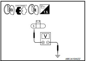
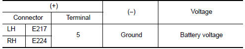
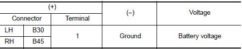
- With EXTERNAL LAMPS ON, check the voltage between the front combination lamp connector and ground.
- With EXTERNAL LAMPS ON, check the voltage between the rear combination lamp connector and ground.
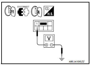
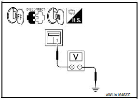
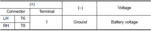
- With EXTERNAL LAMPS ON, check the voltage between the license plate lamp connector and ground.
3.CHECK PARKING LAMP CIRCUIT (OPEN)
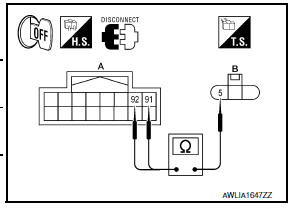
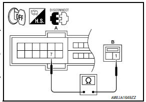
- Turn the ignition switch OFF.
- Disconnect IPDM E/R connector E201.
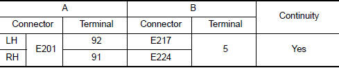
- Check continuity between the IPDM E/R harness connector (A) and the front combination lamp harness connector (B).
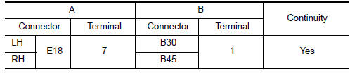
- Check continuity between the IPDM E/R harness connector (A) and the rear combination lamp harness connector (B).
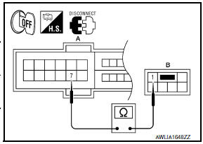
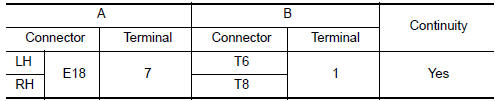
- Check continuity between the IPDM E/R harness connector (A) and the license plate lamp harness connector (B)
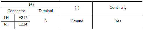
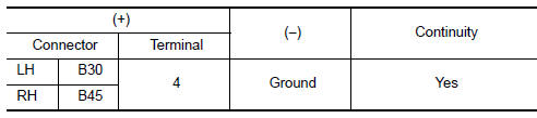
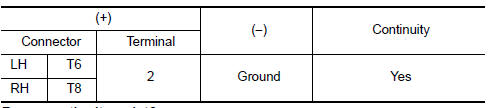
4.CHECK PARKING LAMP GROUND CIRCUIT
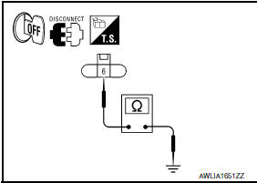
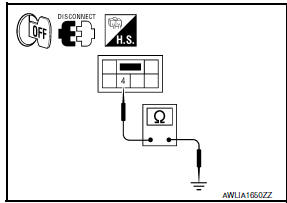
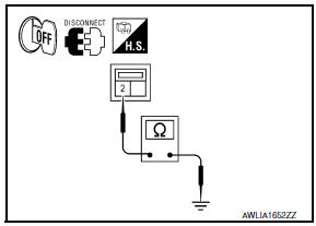
- Check continuity between the front combination lamp harness connector terminal and ground.
- Check continuity between the rear combination lamp harness connector terminal and ground.
- Check continuity between the license plate lamp harness connector terminal and ground.
 Front fog lamp circuit
Description
The IPDM E/R (intelligent power distribution module engine room) controls the
front fog lamp relay based on inputs from the BCM over the CAN communication
lines. When the front fog la ...
 Turn signal lamp circuit
Description
The BCM monitors inputs from the combination switch to determine when to
activate the turn signals. The BCM outputs voltage direction to the left and
right turn signals during turn si ...
Other materials:
Rear view monitor system
System Diagram
System Description
When the shift selector is in the R position, the display shows a view to the
rear of the vehicle. Lines which indicate the vehicle clearance and distances
are also displayed.
Component Parts Location
Tweeter LH M51
Center speaker M130
Tweeter ...
Audio antenna
Location of Antenna
Audio unit
Audio unit antenna feeder
In-line connectors M103, M501
Antenna amp.
Window antenna
Satellite radio tuner
Satellite radio antenna feeder
Satellite radio antenna
Window Antenna Repair
ELEMENT CHECK
Attach probe circuit tester (ohm sett ...
Microphone
Removal and Installation
REMOVAL
Remove the front room/map lamp assembly. Refer to INL-84, "Removal
and Installation".
Detach the microphone connector (A).
Remove the front room/map lamp covers (1), then remove the
map lamp assembly cover (2).
Release the m ...
Nissan Maxima Owners Manual
- Illustrated table of contents
- Safety-Seats, seat belts and supplemental restraint system
- Instruments and controls
- Pre-driving checks and adjustments
- Monitor, climate, audio, phone and voice recognition systems
- Starting and driving
- In case of emergency
- Appearance and care
- Do-it-yourself
- Maintenance and schedules
- Technical and consumer information
Nissan Maxima Service and Repair Manual

0.0119