Nissan Maxima Service and Repair Manual: Turn signal lamp circuit
Description
The BCM monitors inputs from the combination switch to determine when to activate the turn signals. The BCM outputs voltage direction to the left and right turn signals during turn signal operation or both during hazard warning operation. The BCM sends a turn signal indicator request to the combination meter via the CAN communication lines.
The BCM performs the fast flasher operation (fail-safe) if any bulb or harness of the turn signal lamp circuit is open.
NOTE: Turn signal lamp blinks at normal speed when using the hazard warning lamp.
Component Function Check
1.CHECK TURN SIGNAL LAMP
CONSULT
- Select "FLASHER" of BCM (FLASHER) active test item.
- While operating the test item, check that the turn signal lamp blinks.
LH : Turn signal lamp LH blinking
RH : Turn signal lamp RH blinking
OFF : The turn signal lamp
Diagnosis Procedure
1.CHECK TURN SIGNAL LAMP BULB
Check the applicable lamp bulb to be sure the proper bulb standard is in use and the bulb is not open.
2.CHECK TURN SIGNAL LAMP OUTPUT VOLTAGE
- Turn the ignition switch OFF.
- Disconnect front combination lamp connector, door mirror connector (if equipped with turn signal in mirror) and rear combination lamp connector.
- Turn the ignition switch ON.
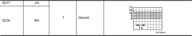
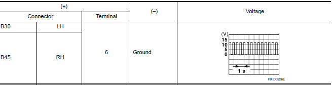
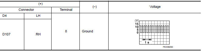
- With turn signal switch operating, check the voltage between the front combination lamp harness connector and ground.
- With turn signal switch operating, check the voltage between the rear combination lamp harness connector and ground.
- With turn signal switch operating, check the voltage between the door mirror (if equipped with turn signals in the mirrors) harness connector and ground.

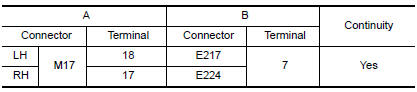
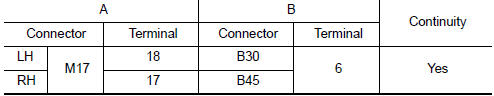
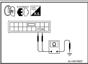
3.CHECK TURN SIGNAL LAMP CIRCUIT FOR OPEN
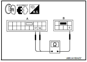
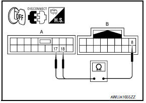
- Turn ignition switch OFF.
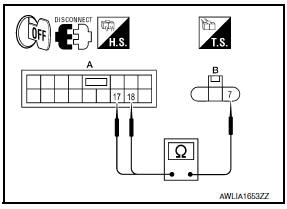
- Disconnect BCM connector M17.
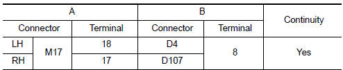
- Check continuity between the BCM harness connector (A) and the front combination lamp connector (B).
- Check continuity between the BCM harness connector (A) and the rear combination lamp harness connector (B).
- Check continuity between the BCM harness connector (A) and the door mirror connector (B) (if equipped with turn signal in mirror).
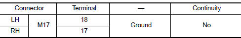
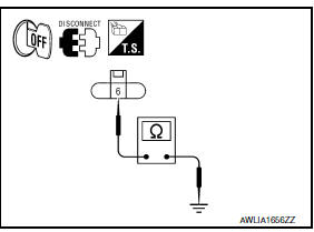
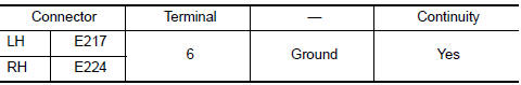
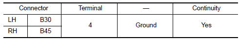
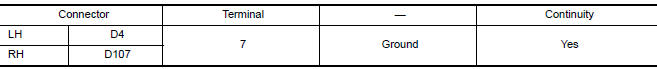
4.CHECK TURN SIGNAL LAMP SHORT CIRCUIT
Check continuity between the BCM harness connector and ground
5.CHECK TURN SIGNAL LAMP GROUND CIRCUIT
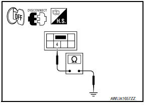
- Turn ignition switch OFF.
- Check continuity between the front combination lamp and ground.
- Check continuity between the rear combination lamp and ground.
- Check continuity between the door mirror and ground (if equipped with turn signal in mirror).
 Parking lamp circuit
Description
The IPDM E/R (intelligent power distribution module engine room) controls the
tail lamp relay based on inputs from the BCM over the CAN communication
lines. When the tail lamp relay i ...
 Optical sensor
Description
The optical sensor converts the outside brightness (lux) to voltage and
transmits the optical sensor signal to the BCM.
Component Function Check
1.CHECK OPTICAL SENSOR SIG ...
Other materials:
Body side trim
Exploded View
Front pillar finisher
Dash side lower finisher
Front kicking plate
Front sill cover
Center pillar lower finisher
Rear sill cover
Rear kicking plate
Rear body side welt
Rear pillar finisher
Screw cover
Center pillar upper finisher
Front seat belt adju ...
P0122, P0123 TP sensor
Description
Electric throttle control actuator consists of throttle control motor,
throttle position sensor, etc. The throttle position sensor responds to
the throttle valve movement.
The throttle position sensor has two sensors. These sensors are a
kind of potentiometer which transfor ...
B2562 Low voltage
DTC Logic
DTC DETECTION LOGIC
DTC CONFIRMATION PROCEDURE
1. DTC CONFIRMATION
Erase DTC.
Turn ignition switch OFF.
Perform the "SELF-DIAG RESULTS" of BCM with CONSULT, after the
ignition switch has been turned ON
for 1.5 seconds or more.
Diagnosis Procedure
1. CHECK ...
Nissan Maxima Owners Manual
- Illustrated table of contents
- Safety-Seats, seat belts and supplemental restraint system
- Instruments and controls
- Pre-driving checks and adjustments
- Monitor, climate, audio, phone and voice recognition systems
- Starting and driving
- In case of emergency
- Appearance and care
- Do-it-yourself
- Maintenance and schedules
- Technical and consumer information
Nissan Maxima Service and Repair Manual

0.0064