Nissan Maxima Service and Repair Manual: Main line between ADP and DLC circuit
Diagnosis Procedure
1.CHECK CONNECTOR
- Turn the ignition switch OFF.
- Disconnect the battery cable from the negative terminal.
- Check the following terminals and connectors for damage, bend and
loose connection (connector side
and harness side).
- Harness connector B1
- Harness connector M6
2.CHECK HARNESS CONTINUITY (OPEN CIRCUIT)
- Disconnect the following harness connectors.
- Harness connectors B208 and B32
- Harness connectors B1 and M6
- Check the continuity between the harness connectors.
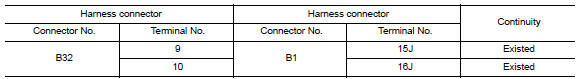
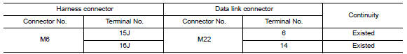
3.CHECK HARNESS CONTINUITY (OPEN CIRCUIT)
Check the continuity between the harness connector and the data link connector.

 Main line between DLC and HVAC circuit
Diagnosis Procedure
1.CHECK HARNESS CONTINUITY (OPEN CIRCUIT)
Turn the ignition switch OFF.
Disconnect the battery cable from the negative terminal.
Disconnect the following harness connector ...
Other materials:
Antenna AMP
Removal and Installation
REMOVAL
Remove the rear pillar finisher RH. Refer to INT-23, "Exploded
View".
Detach the antenna amp. harness clip (A).
Disconnect the harness connectors (B) from the antenna amp.
(1).
Remove the antenna amp. screw (C) and the antenna amp. (1).
INSTALLAT ...
Door lock function
DOOR LOCK AND UNLOCK SWITCH
DOOR LOCK AND UNLOCK SWITCH : System Diagram
DOOR LOCK AND UNLOCK SWITCH : System Description
DOOR LOCK FUNCTION
Functions Available by Operating the Door Lock and Unlock Switches on
Driver Door and Passenger Door
Interlocked with the locking operation o ...
Remote keyless entry receiver
Removal and Installation
REMOVAL
Remove glove box assembly. Refer to IP-20, "Removal and
Installation".
Disconnect the harness connector from the remote keyless
entry receiver (1).
Remove the screw (a) and remote keyless entry receiver (1).
INSTALLATION
Installation ...
Nissan Maxima Owners Manual
- Illustrated table of contents
- Safety-Seats, seat belts and supplemental restraint system
- Instruments and controls
- Pre-driving checks and adjustments
- Monitor, climate, audio, phone and voice recognition systems
- Starting and driving
- In case of emergency
- Appearance and care
- Do-it-yourself
- Maintenance and schedules
- Technical and consumer information
Nissan Maxima Service and Repair Manual

0.006