Nissan Maxima Service and Repair Manual: Main line between DLC and HVAC circuit
Diagnosis Procedure
1.CHECK HARNESS CONTINUITY (OPEN CIRCUIT)
- Turn the ignition switch OFF.
- Disconnect the battery cable from the negative terminal.
- Disconnect the following harness connectors.
- ECM
- A/C auto amp.
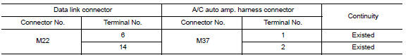
- Check the continuity between the data link connector and the A/C auto amp. harness connector.
 Main line between ADP and DLC circuit
Diagnosis Procedure
1.CHECK CONNECTOR
Turn the ignition switch OFF.
Disconnect the battery cable from the negative terminal.
Check the following terminals and connectors for damage, bend and ...
 Main line between HVAC and A-bag circuit
Diagnosis Procedure
1.CHECK HARNESS CONTINUITY (OPEN CIRCUIT)
Turn the ignition switch OFF.
Disconnect the battery cable from the negative terminal.
Disconnect the following harness connector ...
Other materials:
Maintenance under severe operating conditions
Severe driving conditions
The maintenance intervals shown on the preceding pages are for normal
operating conditions. If the vehicle is mainly operated under severe driving
conditions as shown below, more frequent maintenance must be performed on the
following items as shown in the table.
...
Radius rod
Removal and Installation
Removal
Remove the rear wheel and tire using power tool. Refer to WT-60,
"Adjustment".
Remove the radius rod nut and bolt from the rear axle housing
using power tools.
Remove the radius rod bolt from the rear suspension member using power
tools.
Remove th ...
Both side headlamps (LO) are not turned on
Description
The headlamps (both sides) do not turn ON in any lighting switch setting.
Diagnosis Procedure
1.CHECK COMBINATION SWITCH (LIGHTING AND TURN SIGNAL SWITCH)
Check the combination switch (lighting and turn signal switch
2.CHECK HEADLAMP (LO) REQUEST SIGNAL INPUT
CONSULT DATA MONITOR
...
Nissan Maxima Owners Manual
- Illustrated table of contents
- Safety-Seats, seat belts and supplemental restraint system
- Instruments and controls
- Pre-driving checks and adjustments
- Monitor, climate, audio, phone and voice recognition systems
- Starting and driving
- In case of emergency
- Appearance and care
- Do-it-yourself
- Maintenance and schedules
- Technical and consumer information
Nissan Maxima Service and Repair Manual

0.0056