Nissan Maxima Service and Repair Manual: BCM (body control module)
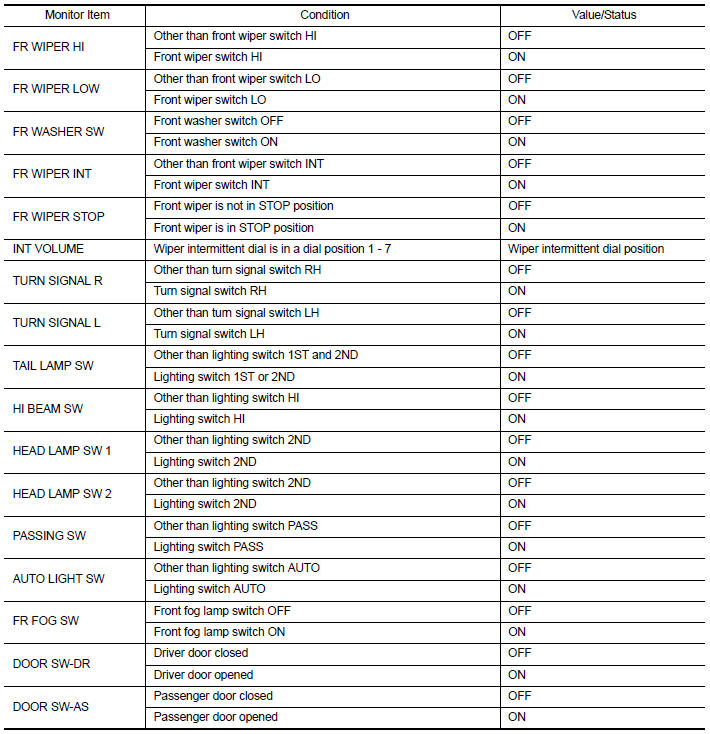
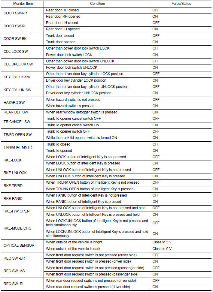
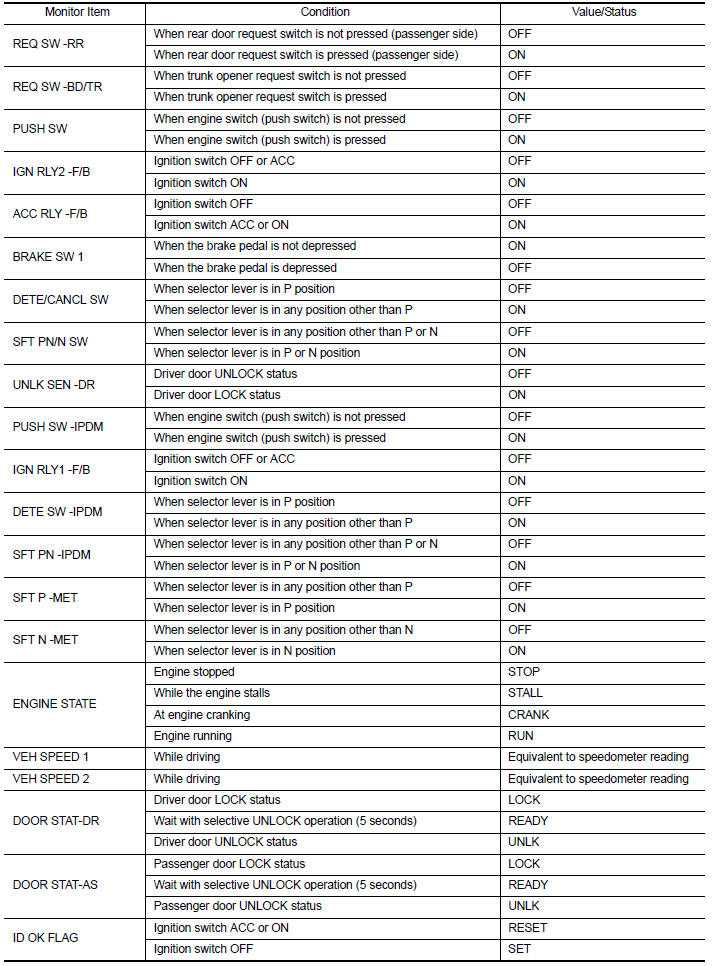
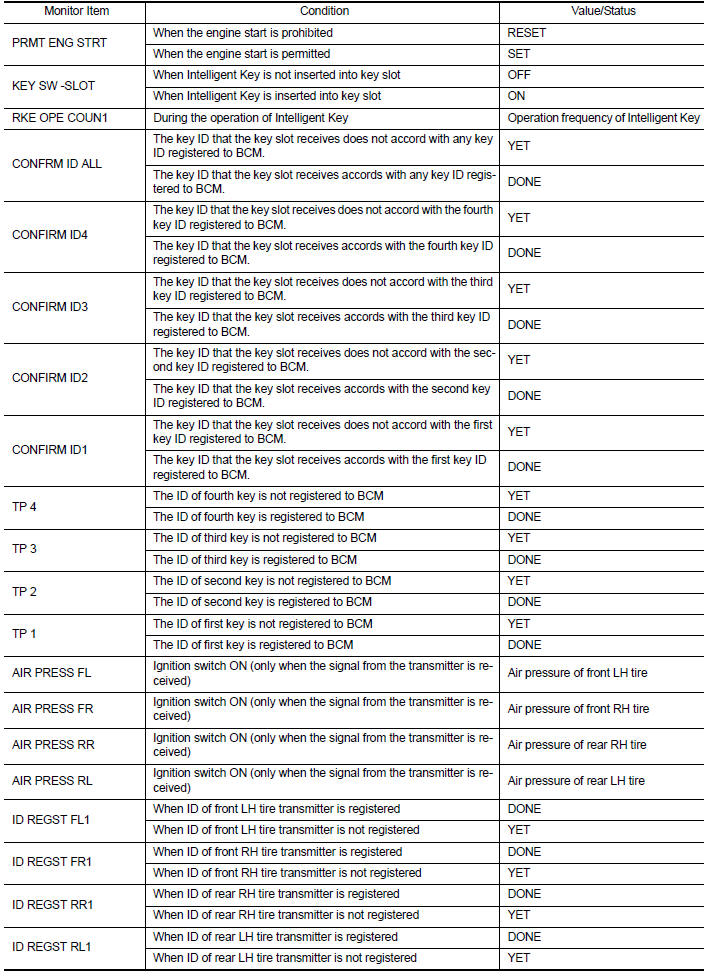
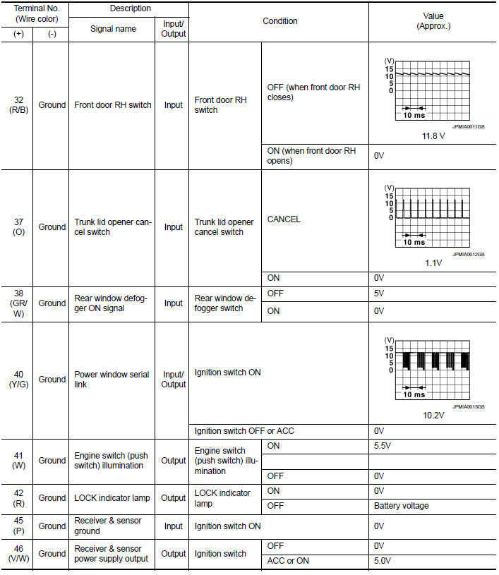
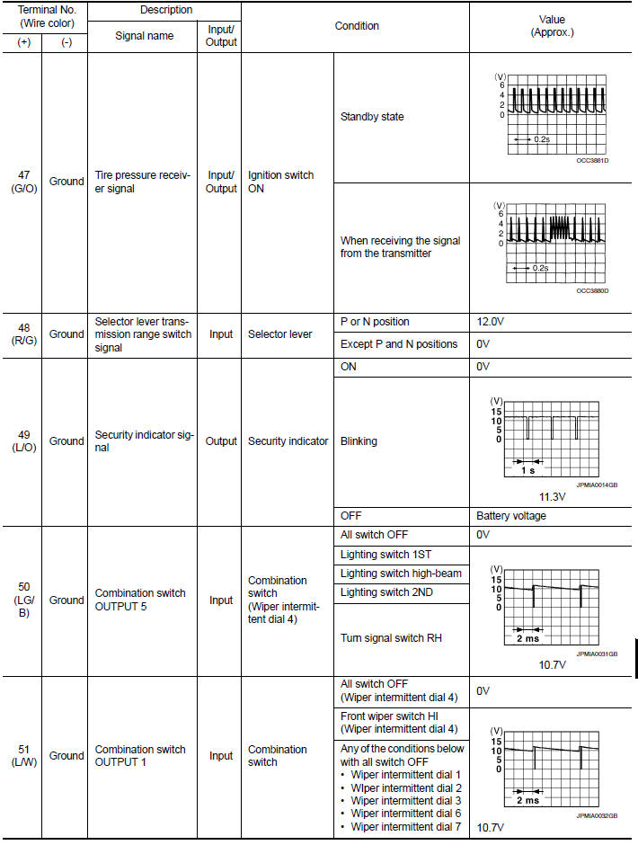
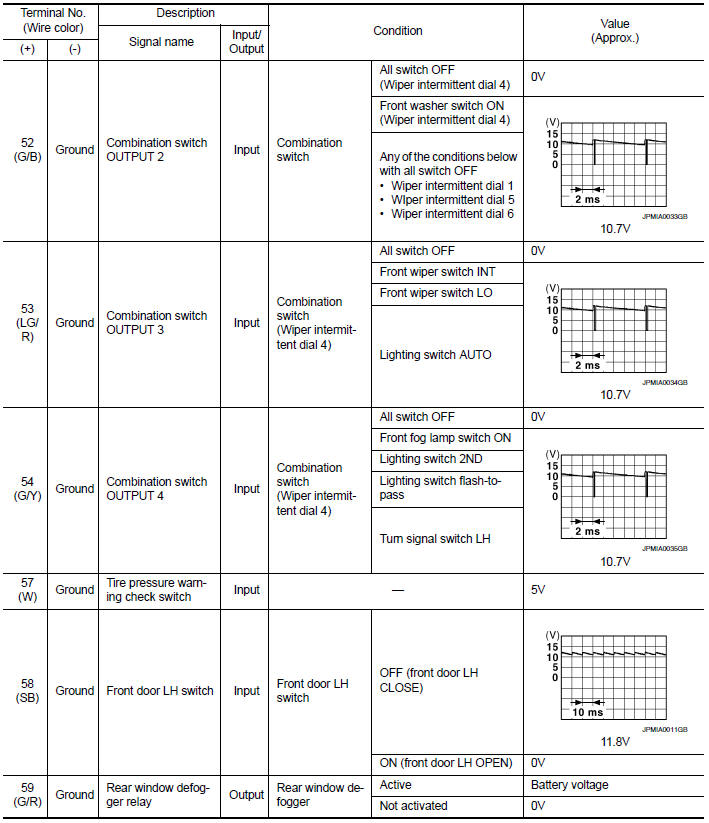
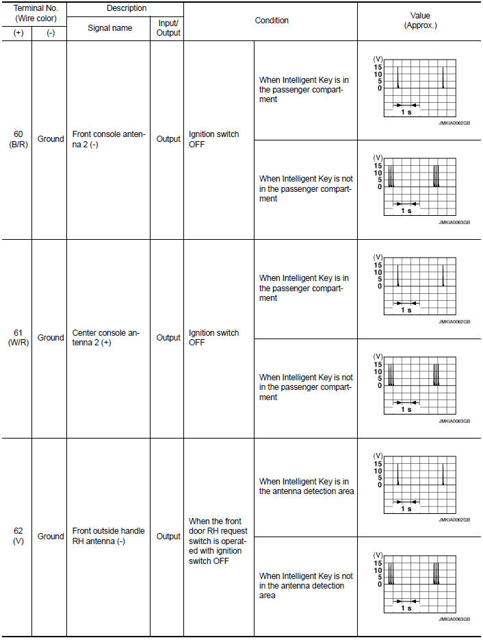
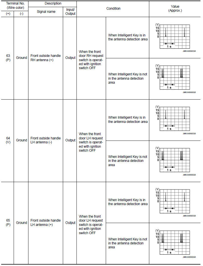
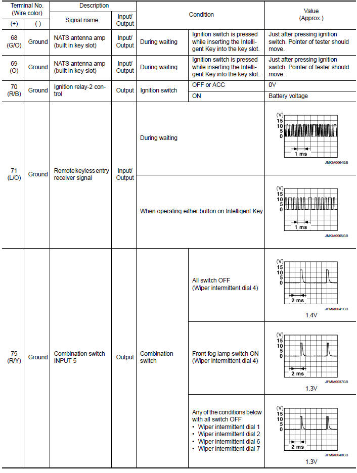
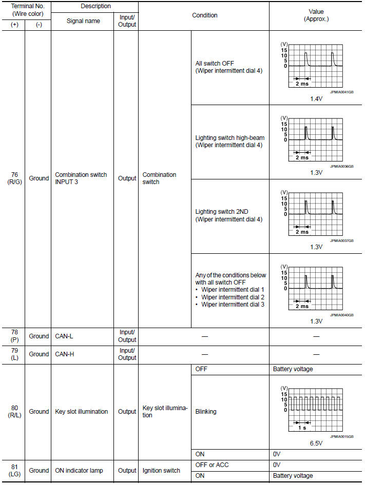
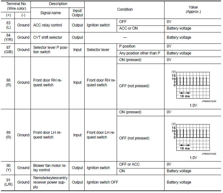
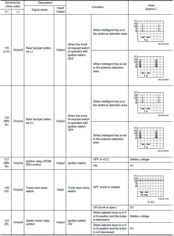
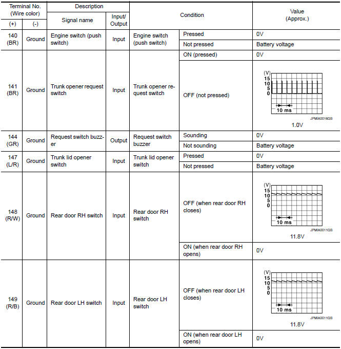
Reference Value
NOTE:
The Signal Tech II Tool (J-50190) can be used to perform the following functions. Refer to the Signal Tech II User Guide for additional information.
- Activate and display TPMS transmitter IDs
- Display tire pressure reported by the TPMS transmitter
- Read TPMS DTCs
- Register TPMS transmitter IDs
- Check Intelligent Key relative signal strength
- Confirm vehicle Intelligent Key antenna signal strength
VALUES ON THE DIAGNOSIS TOOL
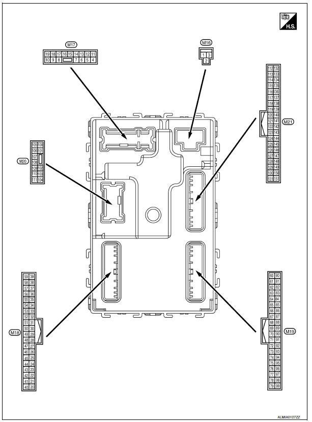
Terminal Layout
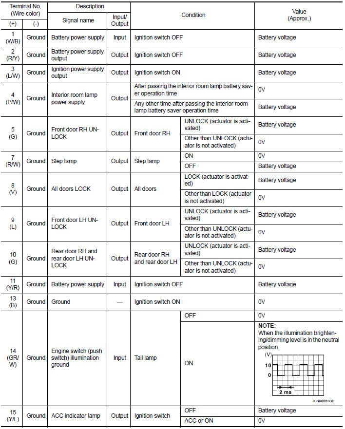
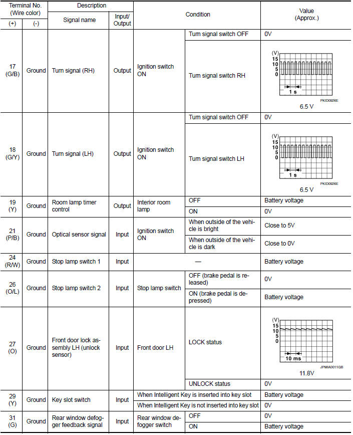
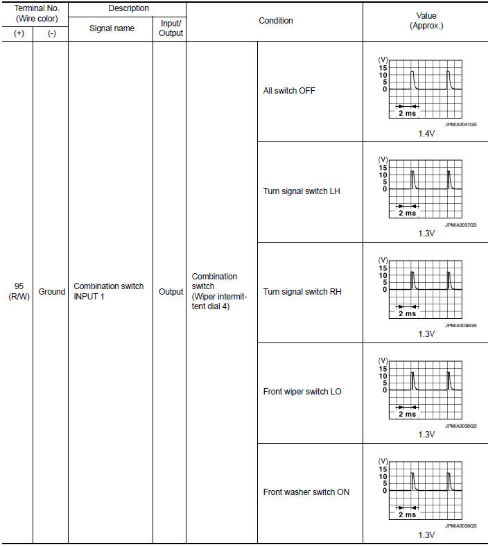
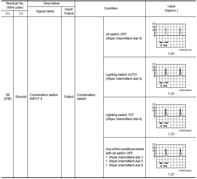
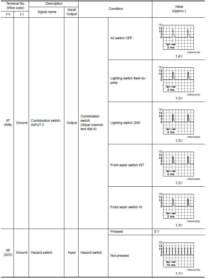
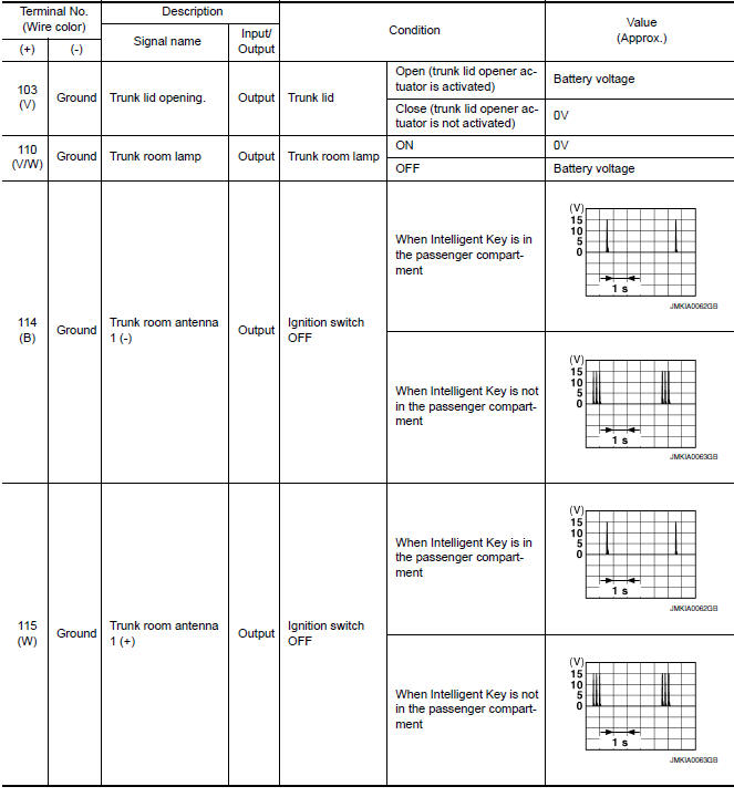
Physical Values
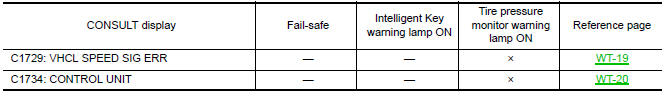
Fail Safe
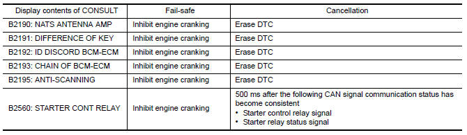
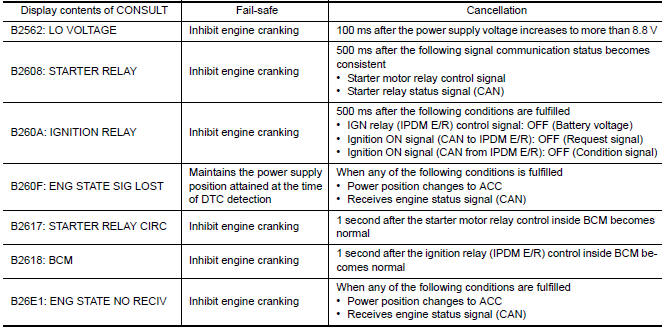
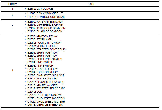
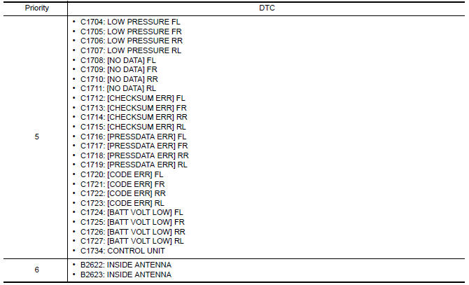
DTC Inspection Priority Chart
If some DTCs are displayed at the same time, perform inspections one by one based on the following priority chart.
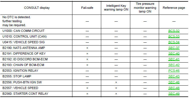
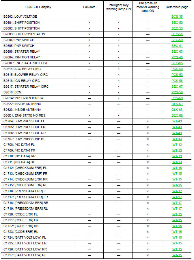
DTC Index
NOTE:
Details of time display
- CRNT: Displays when there is a malfunction now or after returning to the normal condition until turning ignition switch OFF → ON again.
- 1 - 39: Displayed if any previous malfunction is present when current condition is normal. It increases 1 → 2 → 3...38 → 39 after returning to the normal condition whenever ignition switch OFF → ON. The counter remains at 39 even if the number of cycles exceeds it. It is counted from 1 again when turning ignition switch OFF → ON after returning to the normal condition if the malfunction is detected again.
 Combination meter
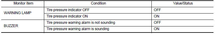
Reference Value
VALUES ON THE DIAGNOSIS TOOL
NOTE:
* The monitor will indicate "OFF" even though the brake warning
lamp is on if either of the following conditions exist:
The parking br ...
 Wiring diagram
WARNING CHIME SYSTEM
Wiring Diagram
...
Other materials:
Rear seat belt
Exploded View
Seat belt retractor assembly (RH)
Seat belt buckle (RH)
Seat belt buckle center
Seat belt buckle (LH)
Seat belt retractor assembly center
Seat belt retractor assembly (LH)
Retractor anchor bolt
Retractor anti-rotation screw
Lower anchor bolt outer
Se ...
Terms
It is important to familiarize yourself with
the following terms before loading your
vehicle:
Curb Weight (actual weight of your
vehicle) - vehicle weight including:
standard and optional equipment, fluids,
emergency tools, and spare tire
assembly. This weight does not include
passen ...
P1709 incompleted data writing
Description
When TCM does not store calibration data (individual
characteristic value) of each solenoid valve that is
stored in the ROM assembly (in the control valve), a malfunction is detected.
DTC Logic
DTC DETECTION LOGIC
DTC CONFIRMATION PROCEDURE
NOTE:
Immediately after performing ...
Nissan Maxima Owners Manual
- Illustrated table of contents
- Safety-Seats, seat belts and supplemental restraint system
- Instruments and controls
- Pre-driving checks and adjustments
- Monitor, climate, audio, phone and voice recognition systems
- Starting and driving
- In case of emergency
- Appearance and care
- Do-it-yourself
- Maintenance and schedules
- Technical and consumer information
Nissan Maxima Service and Repair Manual

0.0073