Nissan Maxima Service and Repair Manual: Combination meter
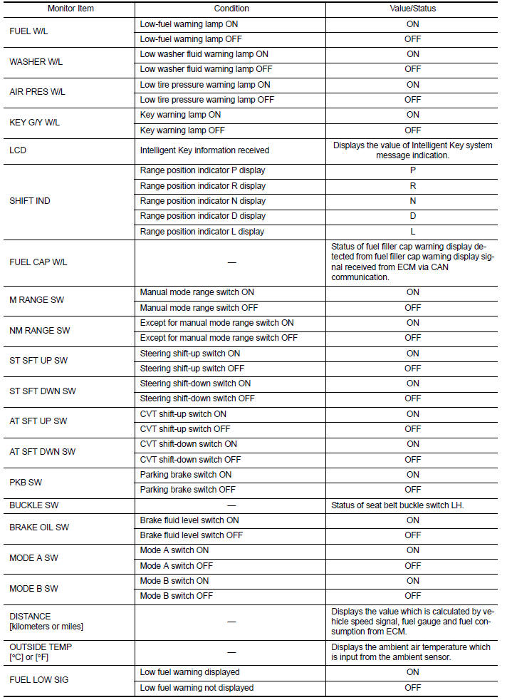
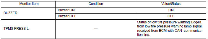
Reference Value
VALUES ON THE DIAGNOSIS TOOL
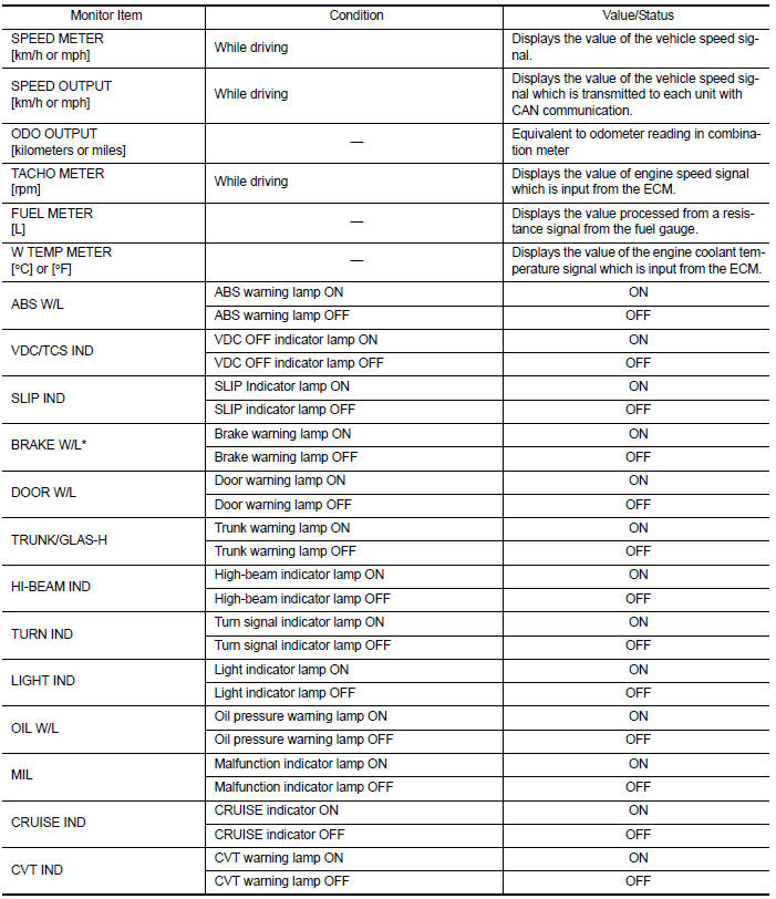
NOTE:
* The monitor will indicate "OFF" even though the brake warning lamp is on if either of the following conditions exist:
- The parking brake is engaged
- The brake fluid level is low
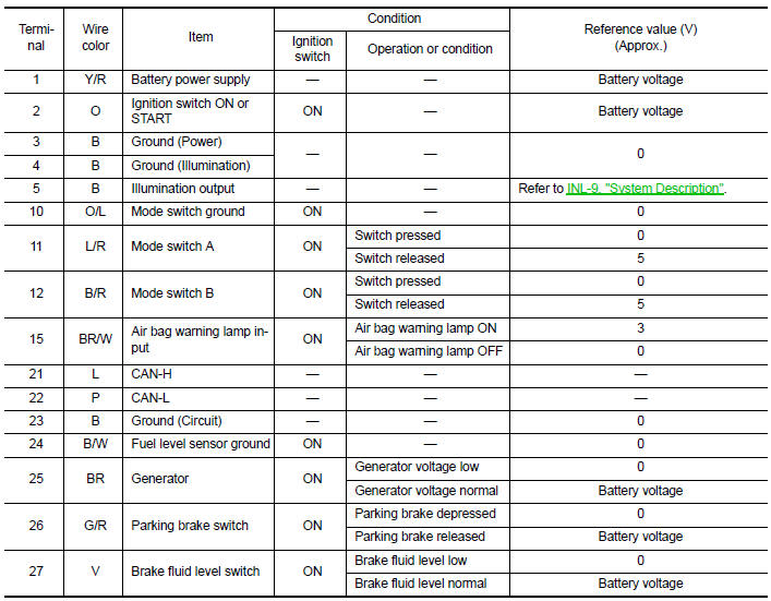
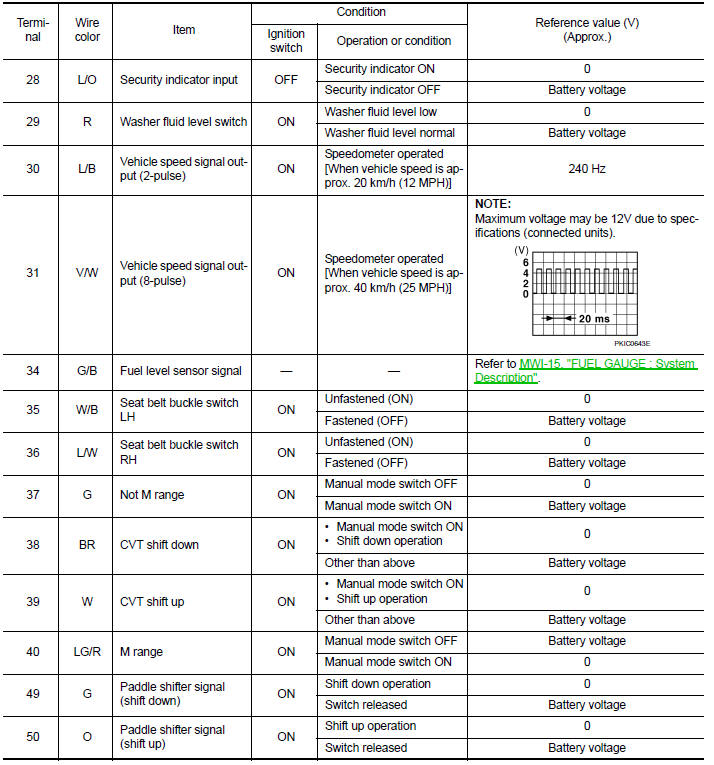
TERMINAL LAYOUT
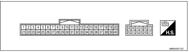
PHYSICAL VALUES
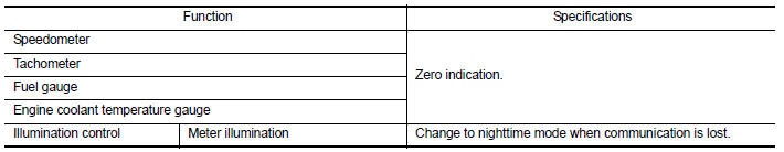
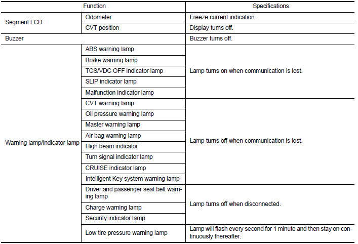
Fail Safe
The combination meter performs a fail-safe operation for the functions listed below when communication is lost.
DTC Index
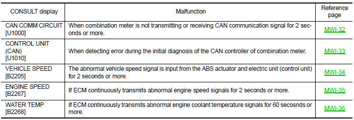
NOTE:
"TIME" indicates the following.
- 0: Indicates that a malfunction is detected at present.
- 1-63: Indicates that a malfunction was detected in the past. (Displays number of ignition switch OFF → ON cycles after malfunction is detected. Self-diagnosis result is erased when "63" is exceeded.)

 BCM (body control module)
Reference Value
NOTE:
The Signal Tech II Tool (J-50190) can be used to perform the
following functions. Refer to the Signal Tech II
User Guide for additional information.
Activate and displa ...
Other materials:
Xenon headlamp
Description
OPERATION
Refer to EXL-10, "Component Description".
PRECAUTIONS FOR TROUBLE
DIAGNOSIS
Installation or removal of the connector must be done with the
lighting switch OFF.
When the lamp is illuminated (when the lighting switch is ON), do
not touch the harness, HID control ...
Power supply and ground circuit
AUDIO UNIT
AUDIO UNIT : Diagnosis Procedure
1.CHECK FUSES
2.POWER SUPPLY CIRCUIT CHECK
Disconnect audio unit connector M132.
Check voltage between the audio unit connector M132 and ground.
3.GROUND CIRCUIT CHECK
Inspect audio unit case ground.
DISPLAY UNIT
DISPLAY UNIT : Dia ...
Child safety rear door lock
Child safety locks help prevent the rear doors
from being opened accidentally, especially when
small children are in the vehicle.
The child safety lock levers are located on the
edge of the rear doors.
When the lever is in the unlock position 2 , the
door can be opened from the outside ...
Nissan Maxima Owners Manual
- Illustrated table of contents
- Safety-Seats, seat belts and supplemental restraint system
- Instruments and controls
- Pre-driving checks and adjustments
- Monitor, climate, audio, phone and voice recognition systems
- Starting and driving
- In case of emergency
- Appearance and care
- Do-it-yourself
- Maintenance and schedules
- Technical and consumer information
Nissan Maxima Service and Repair Manual

0.0057