Nissan Maxima Service and Repair Manual: Wiring diagram
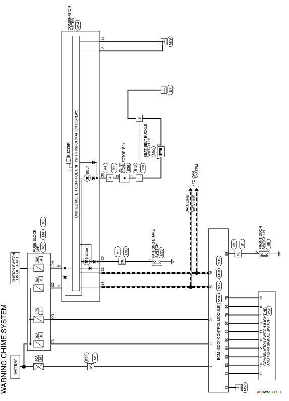
WARNING CHIME SYSTEM
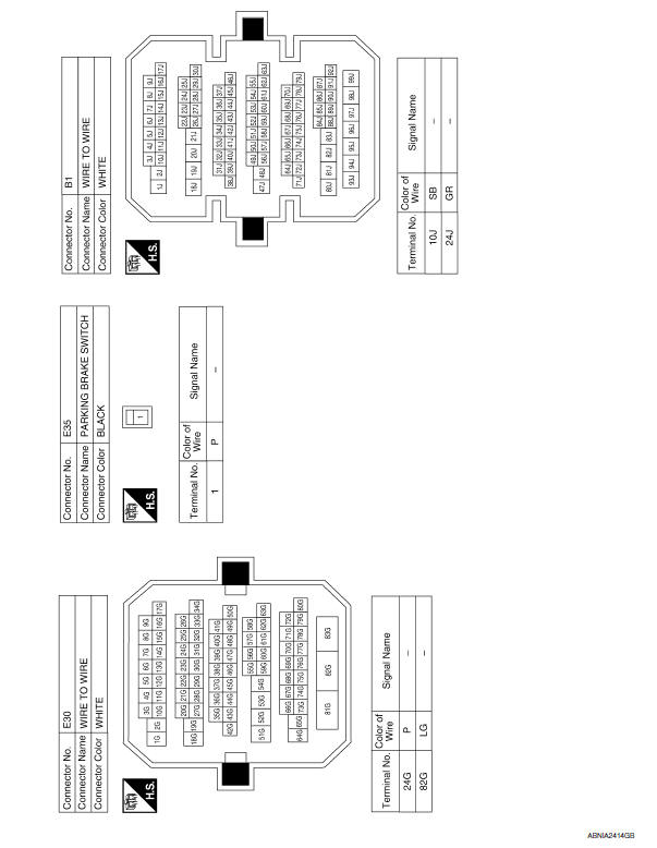
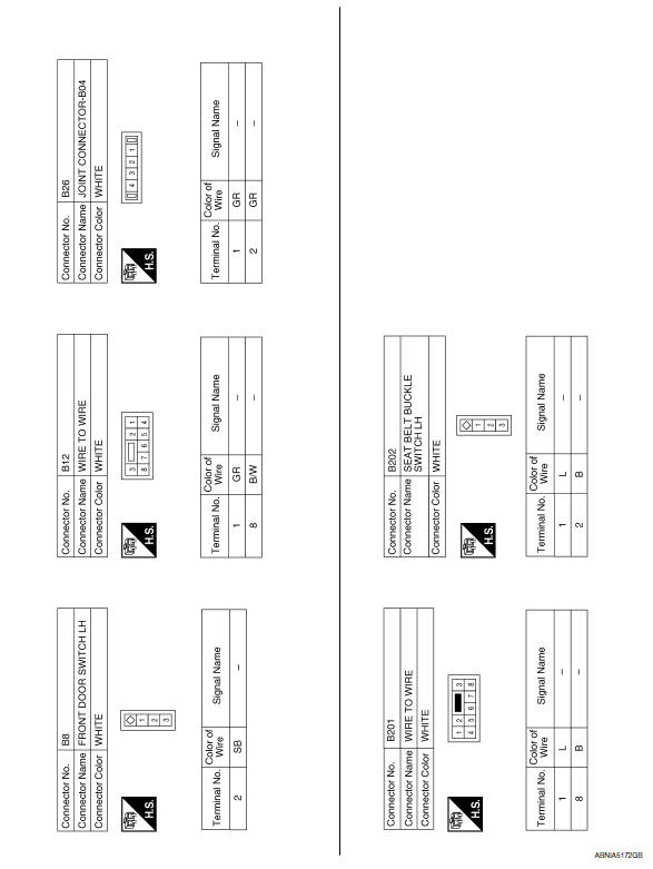
Wiring Diagram
 BCM (body control module)
Reference Value
NOTE:
The Signal Tech II Tool (J-50190) can be used to perform the
following functions. Refer to the Signal Tech II
User Guide for additional information.
Activate and displa ...

Other materials:
Engine control system symptoms
Symptom Table
SYSTEM - BASIC ENGINE CONTROL SYSTEM
1 - 6: The numbers refer to the order of inspection.
(continued on next page)
SYSTEM - ENGINE MECHANICAL & OTHER
1 - 6: The numbers refer to the order of inspection. ...
Remote keyless entry receiver
Removal and Installation
REMOVAL
Remove glove box assembly. Refer to IP-20, "Removal and
Installation".
Disconnect the harness connector from the remote keyless
entry receiver (1).
Remove the screw (a) and remote keyless entry receiver (1).
INSTALLATION
Installation ...
Memory function does not operate
Component Function Check
Symptom
Memory function does not operate normally.
The setting is not maintained. (It returns to the initial
condition.)
1.CHECK OPERATION
Set temperature control dial to 32C (90F).
Press the OFF switch.
Turn the ignition switch OFF.
Turn the ignition ...
Nissan Maxima Owners Manual
- Illustrated table of contents
- Safety-Seats, seat belts and supplemental restraint system
- Instruments and controls
- Pre-driving checks and adjustments
- Monitor, climate, audio, phone and voice recognition systems
- Starting and driving
- In case of emergency
- Appearance and care
- Do-it-yourself
- Maintenance and schedules
- Technical and consumer information
Nissan Maxima Service and Repair Manual

0.006