Nissan Maxima Service and Repair Manual: Power generation voltage variable control system
System Diagram
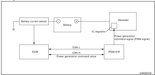
System Description
Power generation variable voltage control system has been adopted. By varying the voltage to the generator, engine load due to power generation of the generator is reduced and fuel consumption is decreased.
NOTE: When any malfunction is detected in the power generation variable voltage control system, power generation is performed according to the characteristic of the IC regulator in the generator.
Component Description
|
Component part |
Description |
| Battery current sensor | The battery current sensor is installed on the battery cable at the negative terminal. The battery current sensor detects the charging/ discharging current of the battery and sends a voltage signal to the ECM according to the current value detected. |
| ECM | The battery current sensor detects the charging/discharging current
of the battery. The ECM judges the battery condition based on
this signal.
The ECM judges whether to request more output via the power generation voltage variable control according to the battery condition. When performing the power generation voltage variable control, the ECM calculates the target power generation voltage according to the battery condition and sends the calculated value as the power generation command value to the IPDM E/R. |
| IPDM E/R | The IPDM E/R converts the received power generation command value into a pulse width modulated (PWM) command signal and sends it to the IC regulator |
| Generator (IC regulator) | The IC regulator controls the power generation voltage by the target
power generation voltage based on the received PWM command
signal.
When there is no PWM command signal, the generator performs the normal power generation according to the characteristic of the IC regulator. |
 Charging system
System Diagram
System Description
The generator provides DC voltage to operate the vehicle's electrical system
and to keep the battery charged.
The voltage output is controlled by the IC re ...
 DTC/circuit diagnosis
CHARGING SYSTEM PRELIMINARY INSPECTION
Diagnosis Procedure
1.CHECK BATTERY TERMINALS CONNECTION
Check if battery terminals are clean and tight
2.CHECK FUSE
Check for blown fuse and fusible link.
...
Other materials:
Unlocking doors
1. Carry the Intelligent Key.
2. Push the door handle request switch.
3. The door on which the request switch was
pressed will unlock and the hazard warning
lights flash once, the outside buzzer sounds
once, and the front and tail lights will turn on
for 30 seconds.
4. Push the door ...
Telescopic motor
Description
The telescopic motor is installed to the steering column assembly.
The telescopic motor is activated with the automatic drive
positioner control unit.
Compresses the steering column by changing the rotation direction
of telescopic motor.
Component Function Check
1.CHECK ...
Blower motor control system
System Diagram
System Description
Fan speed is automatically controlled by the temperature setting, ambient
temperature, in-vehicle temperature,
intake temperature, amount of sunload and air mix door position.
By pressing the AUTO switch, the blower motor starts to gradually increase
a ...
Nissan Maxima Owners Manual
- Illustrated table of contents
- Safety-Seats, seat belts and supplemental restraint system
- Instruments and controls
- Pre-driving checks and adjustments
- Monitor, climate, audio, phone and voice recognition systems
- Starting and driving
- In case of emergency
- Appearance and care
- Do-it-yourself
- Maintenance and schedules
- Technical and consumer information
Nissan Maxima Service and Repair Manual

0.0074