Nissan Maxima Service and Repair Manual: Charging system
System Diagram
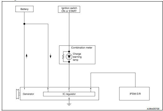
System Description
The generator provides DC voltage to operate the vehicle's electrical system and to keep the battery charged.
The voltage output is controlled by the IC regulator.
Component Description
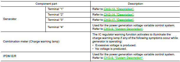

 Power generation voltage variable control system
System Diagram
System Description
Power generation variable voltage control system has been adopted. By varying
the voltage to the generator,
engine load due to power generation of the gener ...
Other materials:
VDC off switch
Description
VDC OFF switch deactivates (turn OFF) the VDC/TCS function when the VDC OFF
switch is pressed.
Component Function Check
1.CHECK VDC OFF SWITCH OPERATION
Operate the VDC OFF switch and check that the VDC OFF indicator lamp in the
combination meter turns on/
off correctly.
D ...
Difference between predicted and actual distances
The displayed guidelines and their locations on
the ground are for approximate reference only.
Objects on uphill or downhill surfaces or projecting
objects will be actually located at distances
different from those displayed in the monitor relative
to the guidelines (refer to illustrations). ...
Wiring diagram
COLOR DISPLAY
Wiring Diagram - Without BOSE Audio System Without Navigation System
...
Nissan Maxima Owners Manual
- Illustrated table of contents
- Safety-Seats, seat belts and supplemental restraint system
- Instruments and controls
- Pre-driving checks and adjustments
- Monitor, climate, audio, phone and voice recognition systems
- Starting and driving
- In case of emergency
- Appearance and care
- Do-it-yourself
- Maintenance and schedules
- Technical and consumer information
Nissan Maxima Service and Repair Manual

0.0063