Nissan Maxima Service and Repair Manual: STRG branch line circuit
Diagnosis Procedure
1.CHECK CONNECTOR
- Turn the ignition switch OFF.
- Disconnect the battery cable from the negative terminal.
- Check the terminals and connectors of the steering angle sensor for damage, bend and loose connection (unit side and connector side).
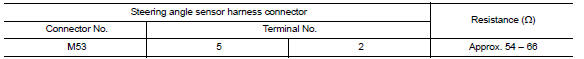
2.CHECK HARNESS FOR OPEN CIRCUIT
- Disconnect the connector of steering angle sensor.
- Check the resistance between the steering angle sensor harness connector terminals.
3.CHECK POWER SUPPLY AND GROUND CIRCUIT
Check the power supply and the ground circuit of the steering angle sensor. Refer to BRC-83, "Wiring Diagram".
 HVAC branch line circuit
Diagnosis Procedure
1.CHECK CONNECTOR
Turn the ignition switch OFF.
Disconnect the battery cable from the negative terminal.
Check the terminals and connectors of the A/C auto amp. for
dam ...
 A-bag branch line circuit
Diagnosis Procedure
WARNING:
Always observe the following items for preventing accidental
activation.
Before servicing, turn ignition switch OFF, disconnect battery negative
terminal, and wa ...
Other materials:
System operation
The automatic drive positioner system will not
work or will stop operating under the following
conditions:
When the vehicle speed is above 0 mph
(0 km/h) or 4 mph (7km/h) for some limited
functions such as linking a key fob to the
meter when the power source is turned on
from off or du ...
Power supply and ground circuit
Diagnosis Procedure
1.CHECK GROUND CONNECTION-I
Turn ignition switch OFF.
Check ground connection E9. Refer to Ground Inspection
2.CHECK ECM GROUND CIRCUIT FOR OPEN AND SHORT-I
Disconnect ECM harness connector.
Check the continuity between ECM harness connector and ground.
Also che ...
Audio display unit
Removal and Installation
Audio display unit bracket
Audio display unit
Cluster lid D
Multifunction switch
Audio display unit bracket screws
Audio display unit screws
Metal Clip
REMOVAL
Remove cluster lid D. Refer to IP-18, "Removal and Installation".
...
Nissan Maxima Owners Manual
- Illustrated table of contents
- Safety-Seats, seat belts and supplemental restraint system
- Instruments and controls
- Pre-driving checks and adjustments
- Monitor, climate, audio, phone and voice recognition systems
- Starting and driving
- In case of emergency
- Appearance and care
- Do-it-yourself
- Maintenance and schedules
- Technical and consumer information
Nissan Maxima Service and Repair Manual

0.0076