Nissan Maxima Service and Repair Manual: DTC/circuit diagnosis
CHARGING SYSTEM PRELIMINARY INSPECTION
Diagnosis Procedure
1.CHECK BATTERY TERMINALS CONNECTION
Check if battery terminals are clean and tight
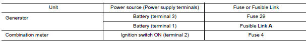
2.CHECK FUSE
Check for blown fuse and fusible link.
3.CHECK GENERATOR GROUND TERMINAL CONNECTION
Check if connector E230 terminal 5 (generator ground harness) is clean and tight.
4.CHECK DRIVE BELT TENSION
Check drive belt tension
 Power generation voltage variable control system
System Diagram
System Description
Power generation variable voltage control system has been adopted. By varying
the voltage to the generator,
engine load due to power generation of the gener ...
 Power generation voltage variable control system operation
inspection
Power generation voltage variable control system operation
inspection
Diagnosis Procedure
CAUTION:
When performing this inspection, always use a charged battery that has completed
the battery inspection.
(When the charging rate of the battery is low, the respons ...
Other materials:
High-mounted stop lamp
Exploded View
Models Without Rear Spoiler
High-mounted stop lamp cover
High-mounted stop lamp bulb
Models With Rear Spoiler
Rear spoiler
High-mounted stop lamp assembly
Removal and Installation
WITHOUT REAR SPOILER
Removal
Slide the high-mounted stop lamp rearwar ...
P0101 MAF sensor
Description
The mass air flow sensor (1) is placed in the stream of intake air. It
measures the intake flow rate by measuring a part of the entire
intake flow. The mass air flow sensor controls the temperature of the
hot wire to a certain amount. The heat generated by the hot wire is ...
ABS
System Diagram
System Description
Anti-Lock Braking System is a function that detects wheel revolution
while braking, electronically controls
braking force, and prevents wheel locking during sudden braking. It improves
handling stability and maneuverability
for avoiding obstacle ...
Nissan Maxima Owners Manual
- Illustrated table of contents
- Safety-Seats, seat belts and supplemental restraint system
- Instruments and controls
- Pre-driving checks and adjustments
- Monitor, climate, audio, phone and voice recognition systems
- Starting and driving
- In case of emergency
- Appearance and care
- Do-it-yourself
- Maintenance and schedules
- Technical and consumer information
Nissan Maxima Service and Repair Manual

0.0067