Nissan Maxima Service and Repair Manual: Steering switch
Description
When one of the steering wheel audio control switches is pushed, the resistance in the steering wheel audio control switch circuit changes, depending on which button is pushed.
Diagnosis Procedure
1.CHECK STEERING SWITCH RESISTANCE
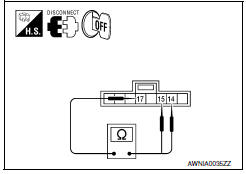
- Disconnect steering switch connector M88.
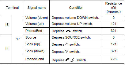
- Check resistance between steering switch connector termina
2.CHECK HARNESS BETWEEN COMBINATION SWITCH (SPIRAL CABLE) AND BLUETOOTH CONTROL UNIT
- Turn ignition switch OFF.
- Disconnect Bluetooth control unit connector B131 and combination switch (spiral cable) connector M30.
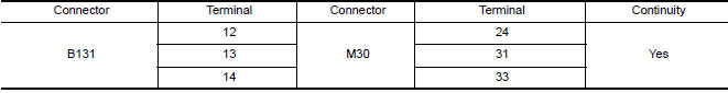
- Check continuity between Bluetooth control unit harness connector B131 and combination switch (spiral cable) harness connector M30.
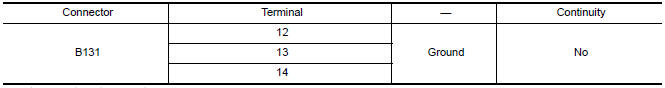
- Check continuity between Bluetooth control unit connector B131 and ground.
3.CHECK HARNESS BETWEEN COMBINATION SWITCH (SPIRAL CABLE) AND AUDIO UNIT
- Disconnect audio unit connector M135.
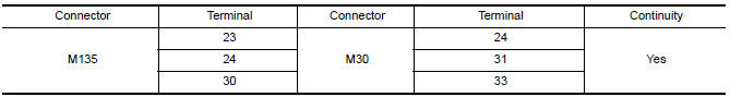
- Check continuity between audio unit harness connector M135 and combination switch (spiral cable) harness connector M30.
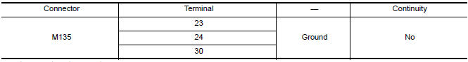
- Check continuity between audio unit connector M135 and ground.
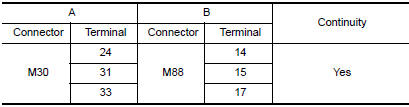
4.COMBINATION SWITCH (SPIRAL CABLE) CHECK
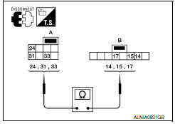
- Check continuity between combination switch (spiral cable) harness connector M30 (A) and M88 (B).
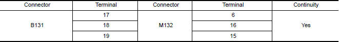
5.CHECK HARNESS BETWEEN BLUETOOTH CONTROL UNIT AND AUDIO UNIT
- Disconnect audio unit connector M132.
- Check continuity between Bluetooth control unit harness connector B131 and audio unit harness connector M132.
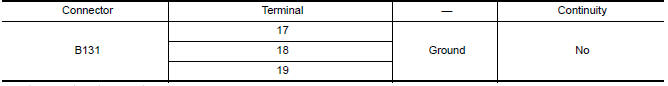
- Check continuity between Bluetooth control unit connector B131 and ground.
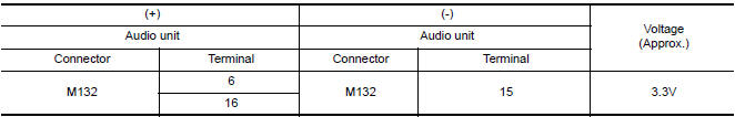
6.CHECK AUDIO UNIT VOLTAGE
- Connect audio unit harness connector M132 and Bluetooth control unit harness connector B131.
- Turn ignition switch ON.
- Check voltage between audio unit harness connector M132 terminals.
 AMP on signal circuit
Description
When the audio system is turned on, a voltage signal is supplied from the
audio unit to the BOSE speaker amp. When this signal is received, the BOSE
speaker amp. will turn on.
Diagno ...
 Microphone signal circuit
Description
Voice signals are transmitted from the microphone to the Bluetooth control
unit using the microphone signal circuits.
Diagnosis Procedure
1.CHECK HARNESS BETWEEN BLUETOOTH CONTROL UNI ...
Other materials:
DLC branch line circuit
Diagnosis Procedure
1.CHECK CONNECTOR
Turn the ignition switch OFF.
Disconnect the battery cable from the negative
terminal.
Check the terminals and connectors of the data
link connector for damage, bend and loose connection
(connector side and harn ...
Seat belt buckle switch signal circuit
Description
Transmits a seat belt buckle switch LH signal to the combination meter.
Component Function Check
1. CHECK COMBINATION METER INPUT SIGNAL
Start engine.
Monitor seat belt warning lamp while fastening and unfastening the
driver seat belt.
Diagnosis Procedure
Regarding Wiring ...
Multiport fuel injection system
System Diagram
System Description
INPUT/OUTPUT SIGNAL CHART
*1: This sensor is not used to control the engine system under normal
conditions.
*2: This signal is sent to the ECM via the CAN communication line.
*3: ECM determines the start signal status by the signals of engine speed ...
Nissan Maxima Owners Manual
- Illustrated table of contents
- Safety-Seats, seat belts and supplemental restraint system
- Instruments and controls
- Pre-driving checks and adjustments
- Monitor, climate, audio, phone and voice recognition systems
- Starting and driving
- In case of emergency
- Appearance and care
- Do-it-yourself
- Maintenance and schedules
- Technical and consumer information
Nissan Maxima Service and Repair Manual

0.0067