Nissan Maxima Service and Repair Manual: Microphone signal circuit
Description
Voice signals are transmitted from the microphone to the Bluetooth control unit using the microphone signal circuits.
Diagnosis Procedure
1.CHECK HARNESS BETWEEN BLUETOOTH CONTROL UNIT AND MICROPHONE
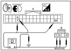
- Turn ignition switch OFF.
- Disconnect Bluetooth control unit connector and microphone connector.
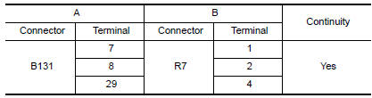
- Check continuity between Bluetooth control unit harness connector B131 (A) and microphone harness connector R7 (B).
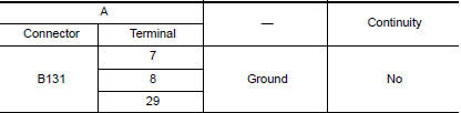
- Check continuity between Bluetooth control unit harness connector B131 (A) and gro
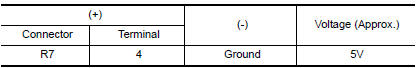
2.CHECK MICROPHONE POWER SUPPLY
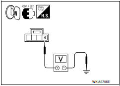
- Connect Bluetooth control unit connector and microphone connector.
- Turn ignition switch ON.
- Check voltage between microphone harness connector R7 terminal 4 and groun
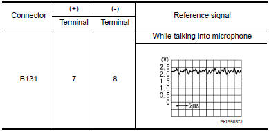
3.CHECK MICROPHONE SIGNAL
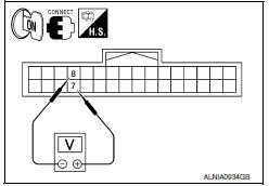
Check signal between Bluetooth control unit harness connector B131 terminals 7 and 8.
 Steering switch
Description
When one of the steering wheel audio control switches is pushed, the
resistance in the steering wheel audio control switch circuit changes,
depending on which button is pushed.
Diagn ...

Other materials:
Manual operation (if so equipped)
Tilt and telescopic operation
Pull the lock lever 1 down:
Adjust the steering wheel up or down in
direction 2 to the desired position.
Adjust the steering wheel forward or backward
in direction 3 to the desired position.
Push the lock lever 1 up firmly to lock the
steering wheel i ...
Maintenance under severe operating conditions
Severe driving conditions
The maintenance intervals shown on the preceding pages are for normal
operating conditions. If the vehicle is mainly operated under severe driving
conditions as shown below, more frequent maintenance must be performed on the
following items as shown in the table.
...
Can communication system
System Description
CAN communication is a multiplex communication system. This enables the
system to transmit and receive large quantities of data at high speed by connecting control units with two
communication lines (CAN-H and CAN-L).
Control units on the CAN network transmit signals usi ...
Nissan Maxima Owners Manual
- Illustrated table of contents
- Safety-Seats, seat belts and supplemental restraint system
- Instruments and controls
- Pre-driving checks and adjustments
- Monitor, climate, audio, phone and voice recognition systems
- Starting and driving
- In case of emergency
- Appearance and care
- Do-it-yourself
- Maintenance and schedules
- Technical and consumer information
Nissan Maxima Service and Repair Manual

0.0055