Nissan Maxima Service and Repair Manual: AMP on signal circuit
Description
When the audio system is turned on, a voltage signal is supplied from the audio unit to the BOSE speaker amp. When this signal is received, the BOSE speaker amp. will turn on.
Diagnosis Procedure
1.CHECK AMP ON SIGNAL (BOSE SPEAKER AMP)
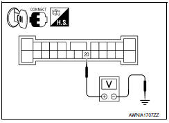
- Turn audio system ON.
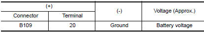
- Check voltage between BOSE speaker amp. harness connector B109 terminal 20 and ground.
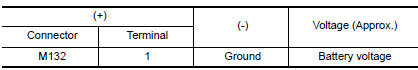
2.CHECK AMP ON SIGNAL (AUDIO UNIT)
Check voltage between audio unit harness connector M132 terminal 1 and ground.
 Subwoofer
Description
The audio unit sends audio signals to the BOSE speaker amp. The BOSE speaker
amp. amplifies the audio signals before sending them to the subwoofers using
the audio signal circuits.
D ...
 Steering switch
Description
When one of the steering wheel audio control switches is pushed, the
resistance in the steering wheel audio control switch circuit changes,
depending on which button is pushed.
Diagn ...
Other materials:
B terminal circuit
Description
"B" terminal circuit supplies power to charge the battery and operate the
vehicle's electrical system.
Diagnosis Procedure
1.CHECK "B" TERMINAL CONNECTION
Turn ignition switch OFF.
Check if "B" terminal is clean and tight
2.CHECK "B" TERMINAL CIRCUIT
Check voltage between ...
P0138, P0158 HO2S2
Description
The heated oxygen sensor 2, after three way catalyst (manifold),
monitors the oxygen level in the exhaust gas on each bank.
Even if switching characteristics of the air fuel ratio (A/F) sensor 1
are shifted, the air-fuel ratio is controlled to stoichiometric, by the signal
...
Door lock function
DOOR LOCK AND UNLOCK SWITCH
DOOR LOCK AND UNLOCK SWITCH : System Diagram
DOOR LOCK AND UNLOCK SWITCH : System Description
DOOR LOCK FUNCTION
Functions Available by Operating the Door Lock and Unlock Switches on
Driver Door and Passenger Door
Interlocked with the locking operation o ...
Nissan Maxima Owners Manual
- Illustrated table of contents
- Safety-Seats, seat belts and supplemental restraint system
- Instruments and controls
- Pre-driving checks and adjustments
- Monitor, climate, audio, phone and voice recognition systems
- Starting and driving
- In case of emergency
- Appearance and care
- Do-it-yourself
- Maintenance and schedules
- Technical and consumer information
Nissan Maxima Service and Repair Manual

0.0078