Nissan Maxima Service and Repair Manual: Subwoofer
Description
The audio unit sends audio signals to the BOSE speaker amp. The BOSE speaker amp. amplifies the audio signals before sending them to the subwoofers using the audio signal circuits.
Diagnosis Procedure
1.CONNECTOR CHECK
Check the audio unit, BOSE speaker amp. and subwoofer connectors for the following:
- Proper connection
- Damage
- Disconnected or loose terminals
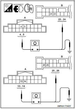
2.HARNESS CHECK
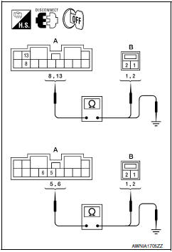
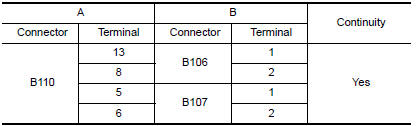
- Disconnect BOSE speaker amp. connector B110 and suspect rear subwoofer connector.
- Check continuity between BOSE speaker amp. harness connector B110 (A) and suspect rear subwoofer harness connector (B).
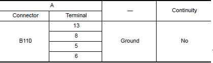
- Check continuity between BOSE speaker amp. harness connector B110 (A) and ground.
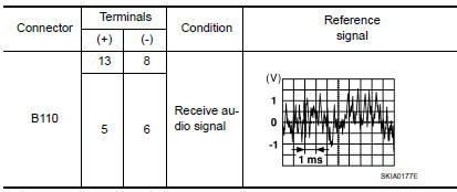
3.REAR SUBWOOFER SIGNAL CHECK
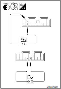
- Connect BOSE speaker amp. connector B110 and suspect rear subwoofer connector.
- Turn ignition switch to ACC.
- Push POWER switch.
- Check the signal between BOSE speaker amp. harness connector B110 terminals with CONSULT or oscilloscope.
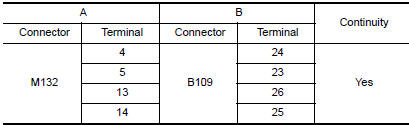
4.HARNESS CHECK
- Disconnect audio unit connector M132 and BOSE speaker amp.
connector B109.
- Check continuity between audio unit harness connector M132 (A) and BOSE speaker amp. harness connector B109 (B).
- Check continuity between audio unit harness connector M132 (A) terminal and ground.

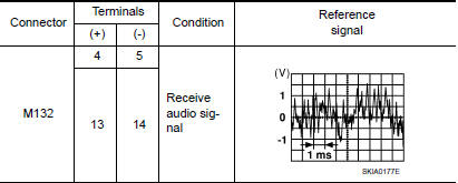
5.REAR SUBWOOFER SIGNAL CHECK
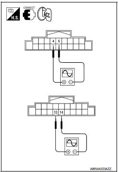
- Connect audio unit connector M132 and BOSE speaker amp.
connector B109.
- Turn ignition switch to ACC.
- Push POWER switch.
- Check the signal between audio unit harness connector terminals with CONSULT or oscilloscope.
 Rear door speaker
Description
The audio unit sends audio signals to the BOSE speaker amp. The BOSE speaker
amp. amplifies the audio signals before sending them to the rear door
speakers using the audio signal circ ...
 AMP on signal circuit
Description
When the audio system is turned on, a voltage signal is supplied from the
audio unit to the BOSE speaker amp. When this signal is received, the BOSE
speaker amp. will turn on.
Diagno ...
Other materials:
Daytime running light system
The LED portion of the headlights automatically
illuminate at 100% intensity when the engine is
started and the parking brake released. The daytime
running lights operate with the headlight
switch in the OFF position. When you turn the
headlight switch to the position for
full
illumination t ...
Microphone
Removal and Installation
REMOVAL
Remove the front room/map lamp assembly. Refer to INL-84, "Removal and
Installation".
Detach the microphone connector (A).
Remove the front room/map lamp covers (1), then remove the
map lamp assembly cover (2).
Release t ...
How to switch the display
With the ignition switch in the ON position, press
the CAMERA button or move the shift lever to the
R (Reverse) position to operate the Around
View Monitor.
The Around View Monitor displays different
split screen views depending on the position of
the shift lever. Press the CAMERA button to
...
Nissan Maxima Owners Manual
- Illustrated table of contents
- Safety-Seats, seat belts and supplemental restraint system
- Instruments and controls
- Pre-driving checks and adjustments
- Monitor, climate, audio, phone and voice recognition systems
- Starting and driving
- In case of emergency
- Appearance and care
- Do-it-yourself
- Maintenance and schedules
- Technical and consumer information
Nissan Maxima Service and Repair Manual

0.0052