Nissan Maxima Service and Repair Manual: Front seat
Exploded View
DRIVER
Driver Seat - With Climate Controlled Seats
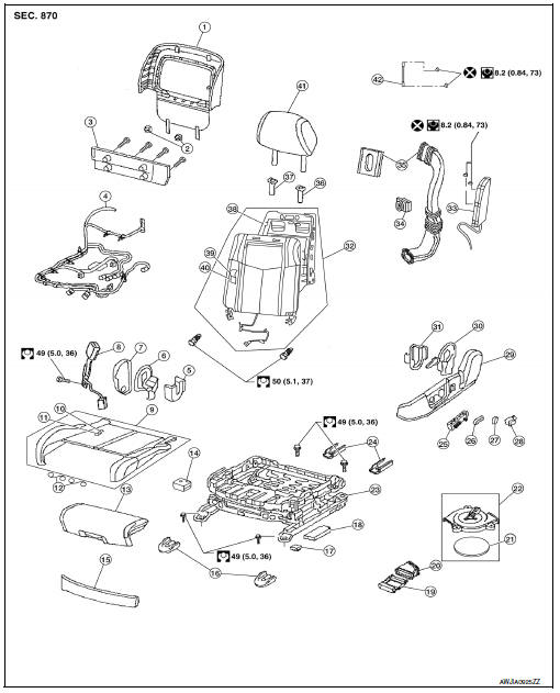
- Seatback board
- Seatback board clip
- Seat cushion lower rear finisher
- Seat harness
- Seat cushion inner finisher inside (RH)
- Recline mechanism inner cover
- Seat cushion outer finisher (RH)
- Seat belt buckle
- Seat cushion assembly
- Seat cushion trim
- Seat cushion pad
- Thigh extension tether
- Thigh extension assembly
- Climate controlled seat control unit
- Seat cushion front finisher
- Front slide cover
- Clip
- Power seat control unit
- Seat cushion thermal electric device (TED)
- Lower seat duct
- Climate controlled seat blower filter
- Climate controlled seat blower motor assembly
- Seat frame assembly
- Rear slide cover
- Power seat switch
- Seat slide and lifter switch knob
- Seat recline knob
- Lumbar support switch
- Seat cushion outer finisher (LH)
- Recline device outer cover
- Seat cushion inner finisher inside (LH)
- Seatback assembly
- Side air bag module
- Seatback thermal electric device (TED)
- Upper seat duct
- Headrest holder (locked)
- Headrest holder (free)
- Seatback frame
- Seatback trim
- Seatback pad
- Headrest
- Chute rod
PASSENGER
Passenger Seat
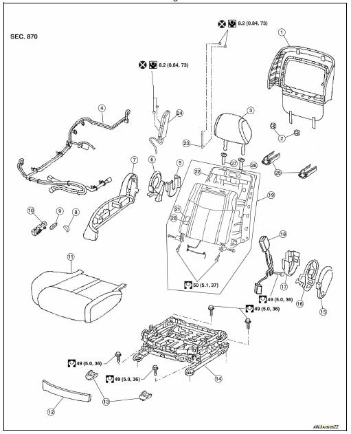
- Seatback board
- Seatback board clips
- Headrest
- Seat harness
- Seat cushion inner finisher inside (RH)
- Recline device inner cover
- Seat cushion outer finisher (RH)
- Seat recline knob
- Seat slide and lifter switch knob
- Power seat switch
- Seat cushion assembly
- Seat cushion front finisher
- Front slide cover
- Seat frame assembly
- Seat cushion outer finisher (LH)
- Recline mechanism inner cover
- Seat cushion inner finisher inside (LH)
- Seat belt buckle
- Seatback assembly
- Seatback pad
- Seatback trim
- Seatback frame
- Chute rod
- Side air bag module
- Rear slide cover
- Headrest holder (locked)
- Headrest holder (free)
Removal and Installation
REMOVAL
WARNING:
Do not leave any objects (screwdrivers, tools, etc.) on the seat during seat repair. It can lead to personal injury if the side air bag module should accidentally deploy.
CAUTION:
- When removing or installing the seat trim, handle it carefully to keep dirt out and to avoid damage.
- When checking the power seat circuit for continuity using a circuit tester, do not confuse its connector with the side air bag module connector. Such an error may cause the air bag module to deploy.
- Do not drop, tilt, or bump the side air bag module while installing the seat. Always handle it with care.
- After the front side air bag module inflates, the front seatback assembly must be replaced.
- When removing and installing the seat, use shop cloths to protect components from damage.
- Before removing the front seat, turn the ignition switch OFF, disconnect both battery terminals and wait at least three minutes.
- Slide the seat to the full forward position.
- Remove the rear slide covers. a. Release the pawls (A).
b. Remove the rear slide covers.
3. Remove the rear mount bolts.
4. Slide the seat to the full rearward position.
5. Remove the front slide covers.
6. Remove the front mount bolts.
7. Disconnect the negative and positive battery terminals and wait at least three minutes. Refer to PG-67, "Removal and Installation (Battery)".
8. Disconnect the harness connector under the seat and remove harness clips.
9. Remove seat from the vehicle.
INSTALLATION
Installation is in the reverse order of removal.
CAUTION:
Make sure that the seat harness or the floor trim is not damaged during installation.
NOTE:
- When installing the LH front seat, tighten the bolts in the order shown.
- When installing the RH front seat, tighten the bolts in the order shown.

 Rear seat
Exploded View - Fixed Seatback
Headrest
Headrest holder (free)
Headrest holder (locked)
Bumper
Seatback assembly
Seatback trim
Seatback pad
Seat cushion trim
Seat cushion p ...
Other materials:
System temporarily unavailable
When radar blockage is detected, the system will
be deactivated automatically. The "Side Radar
Obstruction" warning message will appear and
the BSW/RCTA indicator (white) will blink A in
the vehicle information display.
The system is not available until the conditions no
longer exist.
...
B terminal circuit
Description
"B" terminal circuit supplies power to charge the battery and operate the
vehicle's electrical system.
Diagnosis Procedure
1.CHECK "B" TERMINAL CONNECTION
Turn ignition switch OFF.
Check if "B" terminal is clean and tight
2.CHECK "B" TERMINAL CIRCUIT
Check voltage between ...
Rear door speaker
Description
The AV control unit sends audio signals to the BOSE speaker amp. The BOSE
speaker amp. amplifies the
audio signals before sending them to the rear door speakers using the audio
signal circuits.
Diagnosis Procedure
1.CONNECTOR CHECK
Check the AV control unit, BOSE speaker amp. a ...
Nissan Maxima Owners Manual
- Illustrated table of contents
- Safety-Seats, seat belts and supplemental restraint system
- Instruments and controls
- Pre-driving checks and adjustments
- Monitor, climate, audio, phone and voice recognition systems
- Starting and driving
- In case of emergency
- Appearance and care
- Do-it-yourself
- Maintenance and schedules
- Technical and consumer information
Nissan Maxima Service and Repair Manual

0.0052