Nissan Maxima Service and Repair Manual: Removal and installation
POWER SOCKET
Removal and Installation
POWER SOCKET
NOTE: If the tool does not fit because of the location of the power socket, further disassembly may be required. Refer to IP-14, "Removal and Installation".
Removal
- Remove the fuse for the power socket.
- Insert one end of the Tool (A) into one of the square holes inside the power socket.
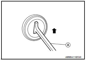
Tool number: - (J-42059)
- Lift up the handle of the Tool until the other end of the Tool is inside the socket and snaps into the other square hole in the power socket.
- Pull the power socket straight out with the Tool.
- Disconnect connector from the power socket.
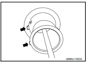
- Remove ring from power socket finisher while pressing pawls.
Installation
Installation is in the reverse order of removal.
NOTE: Make sure to align the tab with the square notched area during installation.
 Preparation
Special Service Tool
The actual shapes of the tools may differ from those illustrated here.
...

Other materials:
The low washer fluid warning continues displaying, or does not display
Description
The warning is still displayed even after
washer fluid is added.
The warning is not displayed even though the
washer tank is empty.
Diagnosis Procedure
1.CHECK WASHER FLUID LEVEL SWITCH SIGNAL CIRCUIT
Check the washer fluid level switch signal cir ...
Body component parts
Underbody Component Parts
Rear seat lower crossmember
Rear floor front
Rear floor front extension
Rear seat crossmember
Front side member rear extension
(LH/RH)
Dash side (LH/RH)
Hoodledge reinforcement (LH/RH)
Hoodledge lower assembly (LH/RH)
Front suspension spring s ...
Preparation
Special Service Tool
The actual shapes of the tools may differ from those illustrated here.
Commercial Service Tool
...
Nissan Maxima Owners Manual
- Illustrated table of contents
- Safety-Seats, seat belts and supplemental restraint system
- Instruments and controls
- Pre-driving checks and adjustments
- Monitor, climate, audio, phone and voice recognition systems
- Starting and driving
- In case of emergency
- Appearance and care
- Do-it-yourself
- Maintenance and schedules
- Technical and consumer information
Nissan Maxima Service and Repair Manual

0.0121