Nissan Maxima Service and Repair Manual: Preparation
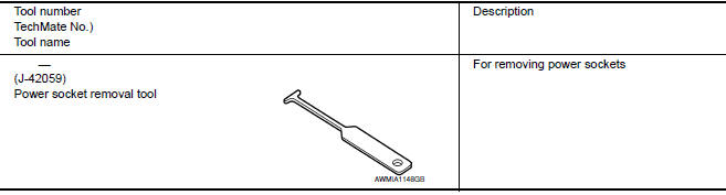
Special Service Tool
The actual shapes of the tools may differ from those illustrated here.
 Wiring diagram
POWER SOCKET
Wiring Diagram
...
 Removal and installation
POWER SOCKET
Removal and Installation
POWER SOCKET
NOTE: If the tool does not fit because of
the location of the power socket, further disassembly may be required. Refer
to IP-14, "Removal and ...
Other materials:
Inspection and adjustment
ADDITIONAL SERVICE WHEN REMOVING BATTERY NEGATIVE TERMINAL
ADDITIONAL SERVICE WHEN REMOVING BATTERY NEGATIVE TERMINAL : Description
Initial setting is necessary when battery terminal is removed.
CAUTION:
The following specified operations are not performed under the
non-initialized condition. ...
Seat belt warning light
Both the driver's and passenger's front seats are
equipped with a seat belt warning light. The
warning light, located on the instrument panel,
will show the status of the driver and passenger
seat belt.
NOTE:
The front passenger seat belt warning light
will not light up if the seat is not ...
Seatback thermal electric device
Description
Provides cooling and heat for the seatback.
Component Function Check
1.CHECK SEATBACK THERMAL ELECTRIC DEVICE FUNCTION
Turn the climate controlled seat switch to the H (Heat) HI
position and check that the seatback thermal
electric device operates correctly.
Turn the clima ...
Nissan Maxima Owners Manual
- Illustrated table of contents
- Safety-Seats, seat belts and supplemental restraint system
- Instruments and controls
- Pre-driving checks and adjustments
- Monitor, climate, audio, phone and voice recognition systems
- Starting and driving
- In case of emergency
- Appearance and care
- Do-it-yourself
- Maintenance and schedules
- Technical and consumer information
Nissan Maxima Service and Repair Manual

0.0057