Nissan Maxima Service and Repair Manual: Wiring diagram
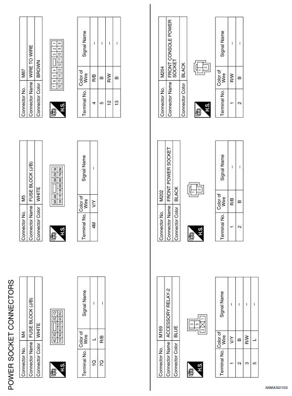
POWER SOCKET
Wiring Diagram
 Precaution
Precaution for Supplemental Restraint System (SRS) "AIR BAG" and
"SEAT BELT PRE-TENSIONER"
The Supplemental Restraint System such as "AIR BAG" and "SEAT BELT
PRE-TENSIONER", used along with a fro ...
 Preparation
Special Service Tool
The actual shapes of the tools may differ from those illustrated here.
...
Other materials:
IPDM E/R (intelligent power distribution module engine room)
Reference Value
VALUES ON THE DIAGNOSIS TOOL
TERMINAL LAYOUT
Fail Safe
CAN COMMUNICATION CONTROL
When CAN communication with ECM and BCM is impossible, IPDM E/R performs
fail-safe control. After CAN
communication recovers normally, it also returns to normal control.
If No ...
Removal and installation
GENERATOR
Exploded View
-3 Tightening order
Generator
B terminal nut
Generator bracket
Front
Removal and Installation
REMOVAL
Remove hoodledge covers (LH/RH).
Remove cooling fan assembly. Refer to CO-16, "Removal and
Installation".
Remove the A/C compre ...
Drive Belts
Checking Drive Belts
Idler pulley
Drive belt
Power steering oil pump
Drive belt auto-tensioner
Crankshaft pulley
Idler pulley
A/C compressor
Generator
Indicator
New drive belt range
Possible use range
View D
Engine front
WARNING: Inspect and check the dri ...
Nissan Maxima Owners Manual
- Illustrated table of contents
- Safety-Seats, seat belts and supplemental restraint system
- Instruments and controls
- Pre-driving checks and adjustments
- Monitor, climate, audio, phone and voice recognition systems
- Starting and driving
- In case of emergency
- Appearance and care
- Do-it-yourself
- Maintenance and schedules
- Technical and consumer information
Nissan Maxima Service and Repair Manual

0.008