Nissan Maxima Service and Repair Manual: Shift control system
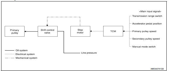
System Diagram
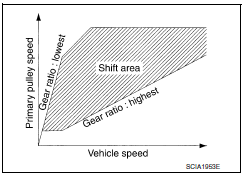
NOTE: The gear ratio is set for each position separately.
System Description
In order to select the gear ratio that can obtain the driving force in accordance with driver's intention and the vehicle condition, TCM monitors the driving conditions, such as the vehicle speed and the throttle position, selects the optimum gear ratio, and determines the gear change steps to the gear ratio. Then TCM sends the command to the step motor, controls the inflow/outflow of line pressure from the primary pulley to determine the position of the moving-pulley and controls the gear ratio.
"D" POSITION
Shifting over all the ranges of gear ratios from the lowest to the highest.
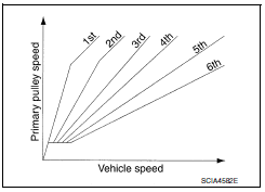
"M" POSITION
By moving the selector lever to + side or - side, the manual mode switch is changed over, and shift change like M/T becomes possible following the changing gear set line step by step.
"DS" POSITION
- When the selector lever is put in the manual shift gate side, the driver can drive more sporty than "D" position.
- "DS" mode can be switched according to the following method.
- When the selector lever is in the "D" position, shifting the selector lever to manual shift gate enables switching to "DS" mode.
- When in "DS" mode, shifting the selector lever to the main gate enables to cancel "DS" mode.
- After switching to manual mode with paddle shifter, switching to "DS" mode can not be enabled even when the selector lever is shifted to the manual gate. (With paddle shifter)
DOWNHILL ENGINE BRAKE CONTROL (AUTO ENGINE BRAKE CONTROL)
When a downhill slope is detected with the accelerator pedal released, the engine brake will be strengthened up by downshifting so as not to accelerate the vehicle more than necessary.
ACCELERATION CONTROL
According to vehicle speed and a change of accelerator pedal angle, driver's request for acceleration and driving scene are judged. This function assists improvement in the acceleration feeling by making the engine speed proportionate to the vehicle speed. And a shift map that can gain a larger driving force is available for compatibility of mileage with driveability.
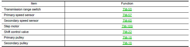
Component Parts Location
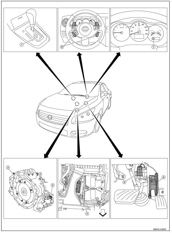
- CVT shift selector assembly (Manual mode select switch and manual mode position select switch)
- Secondary speed sensor
- CVT unit harness connector
- TCM
- Accelerator pedal position (APP) sensor
- Stop lamp switch
- Shift positioner indicator Manual mode indicator DS mode indicator
- Paddle shifters
Component Description
TRANSAXLE ASSEMBLY
EXCEPT TRANSAXLE ASSEMBLY

 Lock-up and select control system
System Diagram
System Description
The torque converter clutch piston in the torque converter is
engaged to eliminate torque converter slip to
increase power transmission efficiency. ...
 Shift lock system
System Diagram
System Description
The selector lever cannot be shifted from "P" position to any other position
unless the ignition switch is in the
ON position and the brake pedal is depressed ...
Other materials:
Sunshade
Exploded View
Center bracket (RH)
Rear sunshade
Front sunshade
Center bracket (LH)
Sunshade carrier assembly Front
Removal and Installation
REMOVAL
Open glass lid and sunshades.
Remove the headlining. Refer to INT-33, "Removal and
Installation".
Release front sunsha ...
How to use the remote keyless entry function
The remote keyless entry function can operate all
door locks using the remote keyless function of
the Intelligent Key. The remote keyless function
can operate at a distance of 33 ft (10 m) away
from the vehicle. The operating distance depends
upon the conditions around the vehicle.
The remot ...
Subwoofer
Description
The AV control unit sends audio signals to the subwoofer amp. The subwoofer
amp. amplifies the audio signals before sending them to the subwoofers using
the audio signal circuits.
Diagnosis Procedure
1.CONNECTOR CHECK
Check the AV control unit, subwoofer amp. and subwoofer connec ...
Nissan Maxima Owners Manual
- Illustrated table of contents
- Safety-Seats, seat belts and supplemental restraint system
- Instruments and controls
- Pre-driving checks and adjustments
- Monitor, climate, audio, phone and voice recognition systems
- Starting and driving
- In case of emergency
- Appearance and care
- Do-it-yourself
- Maintenance and schedules
- Technical and consumer information
Nissan Maxima Service and Repair Manual

0.0063