Nissan Maxima Service and Repair Manual: Lock-up and select control system
System Diagram
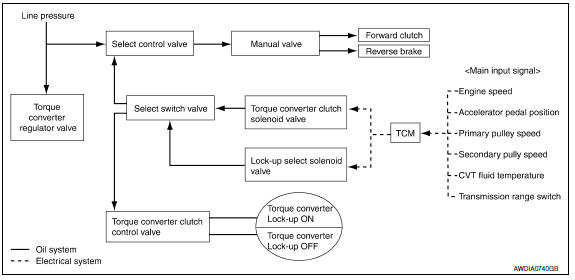
System Description
- The torque converter clutch piston in the torque converter is engaged to eliminate torque converter slip to increase power transmission efficiency.
- The torque converter clutch control valve operation is controlled by the torque converter clutch solenoid valve, which is controlled by a signal from TCM. The torque converter clutch control valve engages or releases the torque converter clutch piston.
- When shifting between "N" ("P") ⇒ "D" ("R"), torque converter clutch solenoid valve controls engagement power of forward clutch and reverse brake.
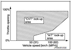
- The lock-up applied gear range was expanded by locking up the torque converter at a lower vehicle speed than conventional CVT models.
TORQUE CONVERTER CLUTCH AND SELECT CONTROL VALVE CONTROL
Lock-up Released
In the lock-up released state, the torque converter clutch control valve is set into the unlocked state by the torque converter clutch solenoid valve and the lock-up apply pressure is drained.
In this way, the torque converter clutch piston is not coupled.
Lock-up Applied
In the lock-up applied state, the torque converter clutch control valve is set into the locked state by the torque converter clutch solenoid valve and lock-up apply pressure is generated.
In this way, the torque converter clutch piston is pressed and coupled.
Select Control
When shifting between "N" ("P") ⇒ "D" ("R"), optimize the operating pressure on the basis of the throttle position, the engine speed, and the secondary pulley (output) revolution speed to lessen the shift shock.
Component Parts Location
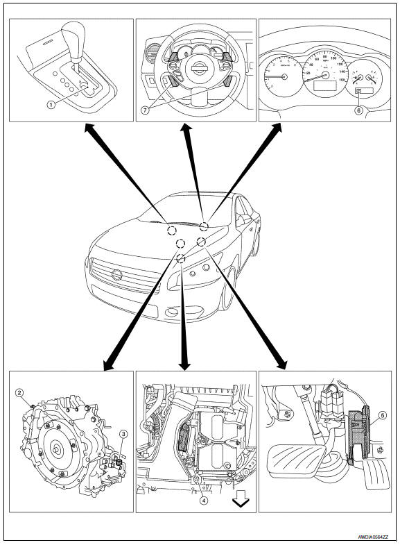
- CVT shift selector assembly (Manual mode select switch and manual mode position select switch)
- Secondary speed sensor
- CVT unit harness connector
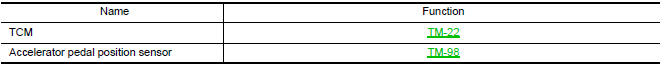
- TCM
- Accelerator pedal position (APP) sensor
- Shift positioner indicator Manual mode indicator DS mode indicator
- Paddle shifters
Component Description
TRANSAXLE ASSEMBLY
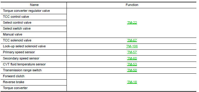
EXCEPT TRANSAXLE ASSEMBLY
 Control system
System Diagram
System Description
The CVT senses vehicle operating conditions through various sensors. It
always controls the optimum shift
position and reduces shifting and lock-up shocks.
T ...
 Shift control system
System Diagram
NOTE: The gear ratio is set for each position separately.
System Description
In order to select the gear ratio that can obtain the driving force in
accordance with driver's inten ...
Other materials:
System description
HEATED STEERING WHEEL
System Diagram
System Description
The heated steering wheel switch controls the heated steering relay. When the
switch is turned on, the relay is energized and the heated steering system
will operate. The heated steering system will turn off when the steering
wheel ...
Emission control information label
The emission control information label is attached
to the underside of the hood as shown.
Tire and loading information label
The cold tire pressure is shown on the Tire and
Loading Information label. The label is located as
shown.
Air conditioner specification label
The air condit ...
Automatic air conditioner system
System Diagram
CONTROL SYSTEM
The control system consists of input sensors, switches, the A/C auto amp.
(microcomputer) and outputs. The
relationship of these components is as shown in the figure below:
System Description
CONTROL OPERATION
Display
The operation status of the HVAC system ...
Nissan Maxima Owners Manual
- Illustrated table of contents
- Safety-Seats, seat belts and supplemental restraint system
- Instruments and controls
- Pre-driving checks and adjustments
- Monitor, climate, audio, phone and voice recognition systems
- Starting and driving
- In case of emergency
- Appearance and care
- Do-it-yourself
- Maintenance and schedules
- Technical and consumer information
Nissan Maxima Service and Repair Manual

0.0055