
Nissan Maxima Service and Repair Manual: Control system
System Diagram
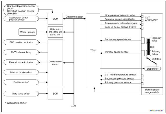
System Description
The CVT senses vehicle operating conditions through various sensors. It always controls the optimum shift position and reduces shifting and lock-up shocks.
TCM FUNCTION
The function of the TCM is to:
- Receive input signals sent from various switches and sensors.
- Determine required line pressure, shifting point, and lock-up operation.
- Send required output signals to the step motor and the respective solenoids.
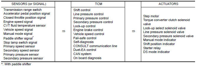
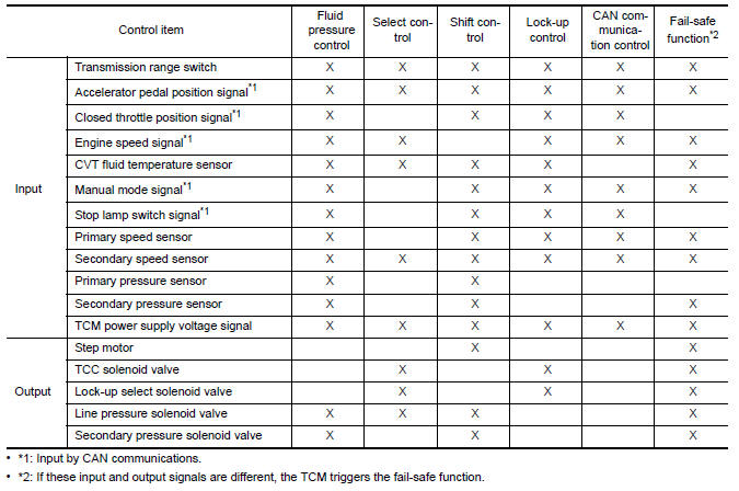
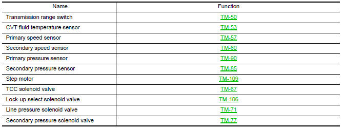
INPUT/OUTPUT SIGNAL OF TCM
Component Parts Location
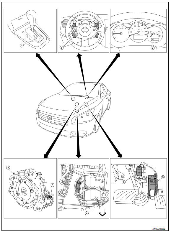
- CVT shift selector assembly (Manual mode select switch and manual mode position select switch)
- Secondary speed sensor
- CVT unit harness connector
- TCM
- Accelerator pedal position (APP) sensor
- Stop lamp switch
- Shift positioner indicator Manual mode indicator DS mode indicator
- Paddle shifters
Component Description
TRANSAXLE ASSEMBLY
EXCEPT TRANSAXLE ASSEMBLY

 Hydraulic control system
System Diagram
System Description
The hydraulic control mechanism consists of the oil pump directly driven by
the engine, the hydraulic control
valve that controls line pressure and transmissi ...
 Lock-up and select control system
System Diagram
System Description
The torque converter clutch piston in the torque converter is
engaged to eliminate torque converter slip to
increase power transmission efficiency. ...
Other materials:
Precaution
PRECAUTIONS
Precaution for Supplemental Restraint System (SRS) "AIR BAG" and
"SEAT BELT PRE-TENSIONER"
The Supplemental Restraint System such as "AIR BAG" and "SEAT BELT
PRE-TENSIONER", used along with a front seat belt, helps to reduce the risk
or severity of injury to the driver and front ...
Can communication circuit
Diagnosis Procedure
1.CONNECTOR INSPECTION
Turn the ignition switch OFF.
Disconnect the battery cable from the negative terminal.
Disconnect all the unit connectors on CAN communication system.
Check terminals and connectors for damage, bend and loose
connection.
2.CHECK HARNESS CON ...
Paddle shifter
Exploded View
Steering column assembly
Paddle shifter (shift-down)
Paddle shifter (shift-up)
Removal and Installation
REMOVAL
Park the vehicle on a level surface.
Remove the driver air bag module. Refer to
SR-12, "Expl ...
Nissan Maxima Owners Manual
- Illustrated table of contents
- Safety-Seats, seat belts and supplemental restraint system
- Instruments and controls
- Pre-driving checks and adjustments
- Monitor, climate, audio, phone and voice recognition systems
- Starting and driving
- In case of emergency
- Appearance and care
- Do-it-yourself
- Maintenance and schedules
- Technical and consumer information
Nissan Maxima Service and Repair Manual

0.0089