Nissan Maxima Service and Repair Manual: Hydraulic control system
System Diagram
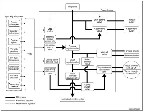
System Description
The hydraulic control mechanism consists of the oil pump directly driven by the engine, the hydraulic control valve that controls line pressure and transmission, and the input signal lin
LINE PRESSURE AND SECONDARY PRESSURE CONTROL
- When an input torque signal equivalent to the engine driving force is transmitted from the ECM to the TCM, the TCM controls the line pressure solenoid valve and secondary pressure solenoid valve.
- Line pressure solenoid valve activates pressure regulator valve, and line pressure from oil pump is adjusted for the optimum driving condition. Secondary pressure is controlled by lowering line pressure.
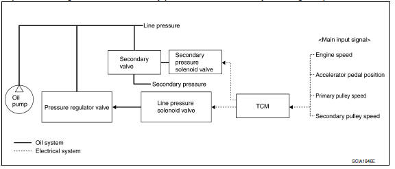
Normal Control
Optimize the line pressure and secondary pressure, depending on driving conditions, on the basis of the throttle position, the engine speed, the primary pulley (input) revolution speed, the secondary pulley (output) revolution speed, the brake signal, the transmission range switch signal, the lock-up signal, the voltage, the target gear ratio, the fluid temperature, and the fluid pressure.
Feedback Control
For the normal fluid control and the select fluid control, secondary pressure is detected for feedback control by using a secondary pressure sensor to set a high-precision secondary pressure.
Component Parts Location
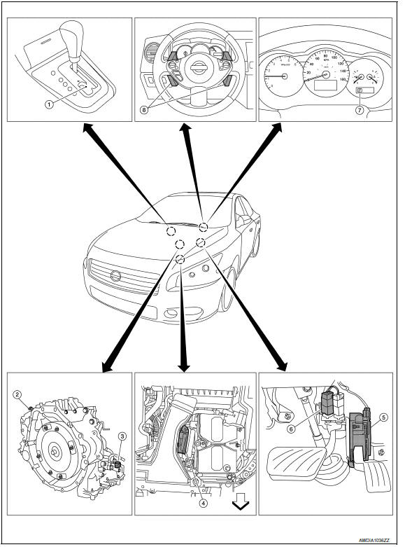
- CVT shift selector assembly (Manual mode select switch and manual mode position select switch)
- Secondary speed sensor
- CVT unit harness connector
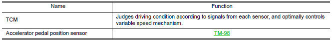
- TCM
- Accelerator pedal position (APP) sensor
- Stop lamp switch
- Shift positioner indicator Manual mode indicator DS mode indicator
- Paddle shifters
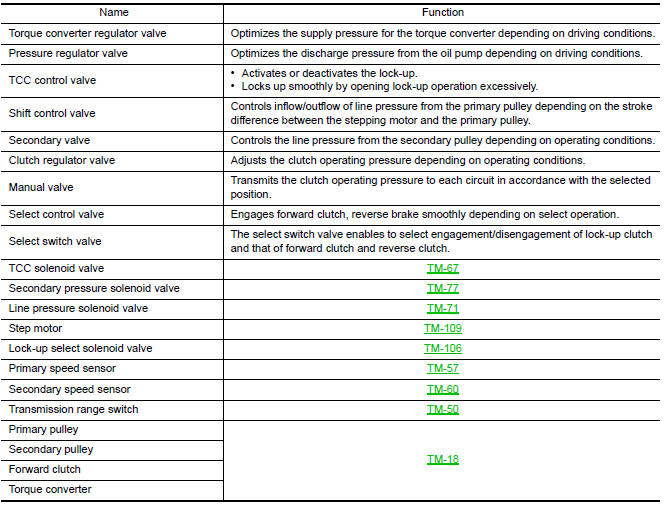
Component Description
TRANSAXLE ASSEMBLY
EXCEPT TRANSAXLE ASSEMBLY
 Mechanical system
Cross-Sectional View
Converter housing
Oil pump
Forward clutch
Reverse brake
Planetary carrier
Primary pulley
Steel belt
Sun ge ...
 Control system
System Diagram
System Description
The CVT senses vehicle operating conditions through various sensors. It
always controls the optimum shift
position and reduces shifting and lock-up shocks.
T ...
Other materials:
U0415 Vehicle speed sig
Description
U0415 is displayed if any unusual condition is present in the reception
status of the vehicle speed signal from
the ABS actuator and electric unit (control unit).
DTC Logic
DTC DETECTION LOGIC
DTC CONFIRMATION PROCEDURE
1. DTC CONFIRMATION
Erase the DTC.
Turn ignition ...
Illumination
Removal and Installation
TRUNK ROOM LAMP
Removal
Release the tab (A), then swing open the lens.
: Front
Remove the bulb (3).
Release the tab (B), then pull trunk room lamp (2) away from
body opening.
Disconnect the connector (1) and remove trunk room lamp
Installation
Install ...
USB connector
Removal and Installation
REMOVAL
Remove the center console assembly. Refer to IP-14, "Removal and
Installation".
Push the pawl from the back of the center console to remove the
USB interface (1).
INSTALLATION
Installation is in the reverse order of removal ...
Nissan Maxima Owners Manual
- Illustrated table of contents
- Safety-Seats, seat belts and supplemental restraint system
- Instruments and controls
- Pre-driving checks and adjustments
- Monitor, climate, audio, phone and voice recognition systems
- Starting and driving
- In case of emergency
- Appearance and care
- Do-it-yourself
- Maintenance and schedules
- Technical and consumer information
Nissan Maxima Service and Repair Manual

0.0062