Nissan Maxima Service and Repair Manual: Mechanical system
Cross-Sectional View
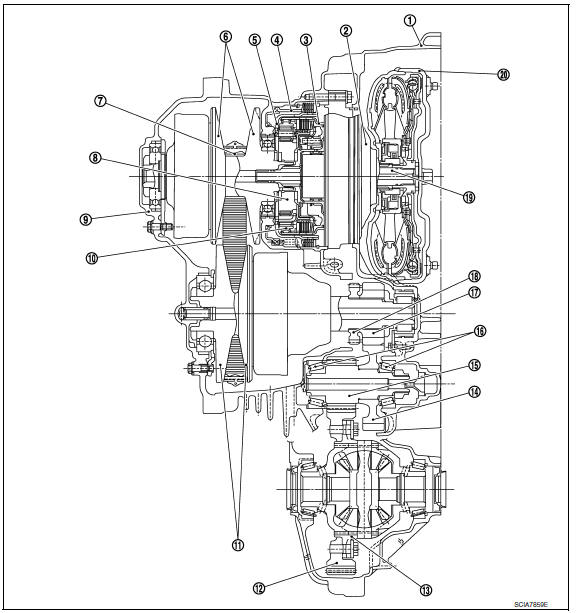
- Converter housing
- Oil pump
- Forward clutch
- Reverse brake
- Planetary carrier
- Primary pulley
- Steel belt
- Sun gear
- Side cover
- Internal gear
- Secondary pulley
- Final gear
- Differential case
- Idler gear
- Reduction gear
- Taper roller bearing
- Output gear
- Parking gear
- Input shaft
- Torque converter
System Diagram
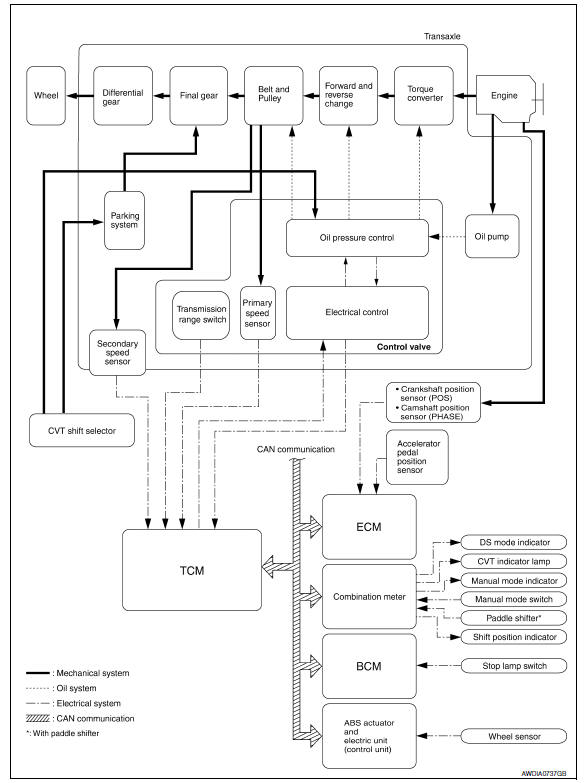
System Description
Transmits the power from the engine to the drive wheel.
Component Parts Location
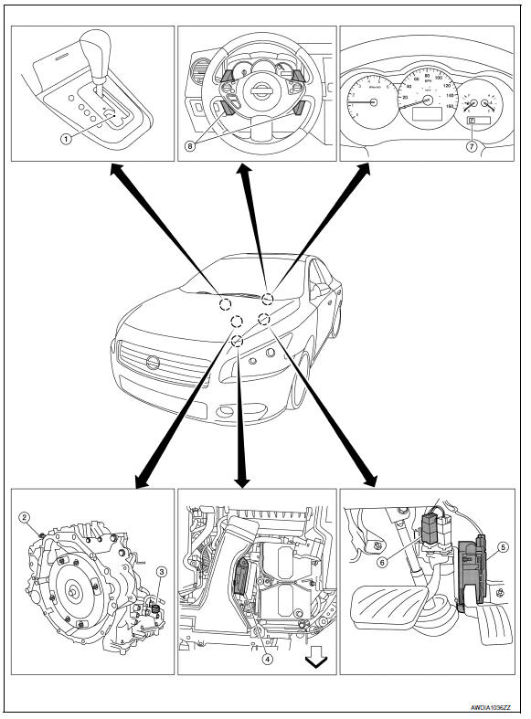
- CVT shift selector assembly (Manual mode select switch and manual mode position select switch)
- Secondary speed sensor
- CVT unit harness connector
- TCM
- Accelerator pedal position (APP) sensor
- Stop lamp switch
- Shift positioner indicator Manual mode indicator DS mode indicator
- Paddle shifters
Component Description
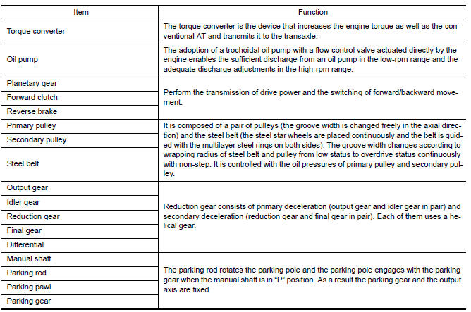
 CVT system
System Diagram
Component Parts Location
CVT shift selector assembly (Manual
mode select switch and manual
mode position select switch)
Secondary speed sensor
CVT ...
 Hydraulic control system
System Diagram
System Description
The hydraulic control mechanism consists of the oil pump directly driven by
the engine, the hydraulic control
valve that controls line pressure and transmissi ...
Other materials:
Microphone signal circuit
Description
Voice signals are transmitted from the microphone to the Bluetooth control
unit using the microphone signal circuits.
Diagnosis Procedure
1.CHECK HARNESS BETWEEN BLUETOOTH CONTROL UNIT AND MICROPHONE
Turn ignition switch OFF.
Disconnect Bluetooth control unit connector and ...
P0172, P0175 fuel injection system function
DTC Logic
DTC DETECTION LOGIC
With the Air/Fuel Mixture Ratio Self-Learning Control, the actual mixture
ratio can be brought closely to the
theoretical mixture ratio based on the mixture ratio feedback signal from A/F
sensor 1. The ECM calculates
the necessary compensation to correct the o ...
Unlocking doors
1. Carry the Intelligent Key.
2. Push the door handle request switch.
3. The door on which the request switch was
pressed will unlock and the hazard warning
lights flash once, the outside buzzer sounds
once, and the front and tail lights will turn on
for 30 seconds.
4. Push the door ...
Nissan Maxima Owners Manual
- Illustrated table of contents
- Safety-Seats, seat belts and supplemental restraint system
- Instruments and controls
- Pre-driving checks and adjustments
- Monitor, climate, audio, phone and voice recognition systems
- Starting and driving
- In case of emergency
- Appearance and care
- Do-it-yourself
- Maintenance and schedules
- Technical and consumer information
Nissan Maxima Service and Repair Manual

0.0059