Nissan Maxima Service and Repair Manual: CVT system
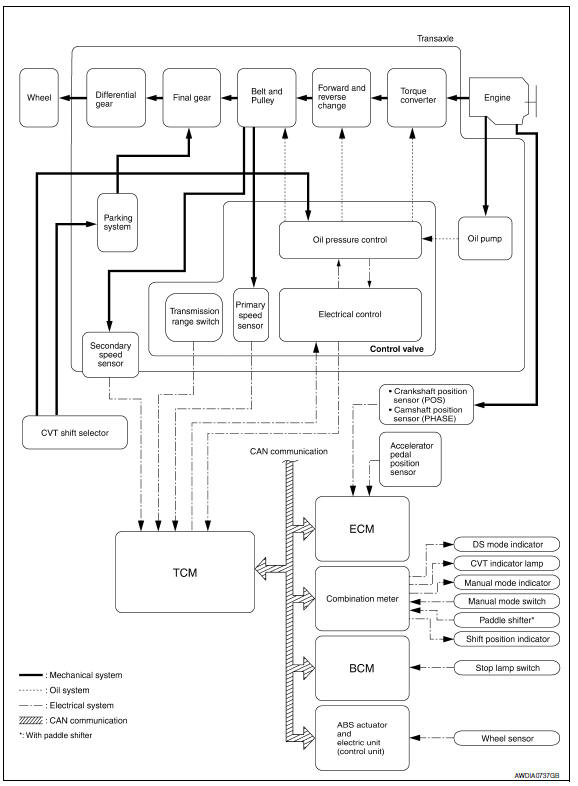
System Diagram
Component Parts Location
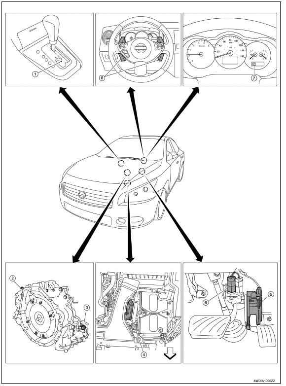
- CVT shift selector assembly (Manual mode select switch and manual mode position select switch)
- Secondary speed sensor
- CVT unit harness connector
- TCM
- Accelerator pedal position (APP) sensor
- Stop lamp switch
- Shift positioner indicator Manual mode indicator DS mode indicator
- Paddle shifters

 Mechanical system
Cross-Sectional View
Converter housing
Oil pump
Forward clutch
Reverse brake
Planetary carrier
Primary pulley
Steel belt
Sun ge ...
Other materials:
Remove
Use the following procedure to remove the head
restraint/headrest:
1. Pull the head restraint/headrest up to the
highest position.
2. Push and hold the lock knob.
3. Remove the head restraint/headrest from
the seat.
4. Store the head restraint/headrest properly in
a secure place so i ...
Horn function
Symptom Table
HAZARD AND HORN REMINDER FUNCTION MALFUNCTION
NOTE:
Before performing the diagnosis in the following table, check
"Work flow". Refer to DLK-9, "Work Flow".
If the following symptoms are detected, check systems shown in
the "Diagnosis/service procedure" column
...
Center speaker
Description
The AV control unit sends audio signals to the BOSE speaker amp. The BOSE
speaker amp. amplifies the
audio signals before sending them to the center speaker using the audio signal
circuits.
Diagnosis Procedure
1.CONNECTOR CHECK
Check the AV control unit, BOSE speaker amp. and s ...
Nissan Maxima Owners Manual
- Illustrated table of contents
- Safety-Seats, seat belts and supplemental restraint system
- Instruments and controls
- Pre-driving checks and adjustments
- Monitor, climate, audio, phone and voice recognition systems
- Starting and driving
- In case of emergency
- Appearance and care
- Do-it-yourself
- Maintenance and schedules
- Technical and consumer information
Nissan Maxima Service and Repair Manual

0.0055